Table of Contents
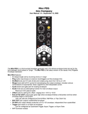
Setting up your Mini PEG
1. Power off your Eurorack system.
2. On the back of the Mini PEG you will see a 16-pin header. Connect one end
of the power cable to a 16-pin Eurorack power header on your power supply
distribution board and the other end to the Mini PEG with the red stripe on
the power cable oriented towards the bottom of the module.
3. Using the included screws, securely attach the Mini PEG to the rails of your
case.
4. Power on your Eurorack system.
Note: The Mini PEG is reverse-polarity protected, but incorrectly connecting any
module in any system can damage other modules on the power bus.
Setting up your Mini PEG! "......................................................................................2
Overview! "................................................................................................................3
Beginning Patch! ".....................................................................................................3
Control Details! ".......................................................................................................4
Ping! "..................................................................................................................4
Div/Mult! "............................................................................................................4
Cycle! "................................................................................................................5
Trigger! "..............................................................................................................5
Shape! "...............................................................................................................5
Scale! "................................................................................................................5
Offset! "...............................................................................................................5
ENV OUT! "..........................................................................................................6
EOF! "..................................................................................................................6
Maximum and Minimum Clock Times! "...................................................................6
Sync and Async Modes! ".........................................................................................7
Changing between Sync and Async Mode! "......................................................7
Cycle Button in Sync and Async mode! "...........................................................7
Modulating Div/Mult in Sync and Async Mode! "................................................7
Using the Trigger jack in Sync and Async Mode! ".............................................8
Quantize Trigger Re-Phasing! ".................................................................................8
Tap Clock Output! "...................................................................................................8
Bus Clock! "..............................................................................................................8
Updating Firmware! "................................................................................................9
Updating Firmware! "..........................................................................................9
Viewing the firmware Version! ".........................................................................10
System Mode! ".......................................................................................................10
Saving the Clock Time and Cycle State! "........................................................10
Electrical and Mechanical Specifications!............................................................12