2CDG941150P0002 / 07.03.2016
Busch/ABB-free@home®
Deutsch
Binäreingang 4-fach, REG
WARNUNG
Bei direktem oder indirektem Kontakt mit spannungs-
führenden Teilen kommt es zu einer gefährlichen
Körperdurchströmung. Elektrischer Schock, Verbren-
nungen oder der Tod können die Folge sein.
ØVor Montage /Demontage Netzspannung freischalten!
Ø Arbeiten am 230 V-Netz nur von Fachpersonal
ausführen lassen.
n Montageanleitung sorgfältig lesen und aufbewahren.
n Weitere Benutzerinformationen unter www.abb.com/freeathome
oder durch Scannen des QR-Codes.
n Informationen zur Systemeinbindung siehe Systemhandbuch
(www.abb.com/freeathome).
Bestimmungsgemäßer Gebrauch
Das Gerät ist zum Erfassen von Spannungen im Bereich
10 ... 230 V AC/DC geeignet.
n Ausführliche Informationen zum Funktionsumfang siehe Tech-
nisches Handbuch (siehe QR-Code)
Technische Daten
Stromversorgung 21 ... 30 V DC
Verlustleistung P Max. 0,1 W
Busanschluss Busanschlussklemme, schraubenlos
0-Signal
1-Signal
0 ... 2 V AC/DC
7 ... 265 V AC/DC
max. Abfragestrom 355 mA
Einschaltstrom je
Ausgang max. 750 mA bei T
u = 60 C°
Anschlussklemme
Ausgang
Schraubklemmen
0,2 ... 2,5 mm² feindrahtig
0,2 ... 4 mm² eindrahtig
Schutzart IP 20 nach EN 60 529
Schutzklasse II nach EN 61 140
Überspannungskategorie
III nach EN 60 664-1
Verschmutzungsgrad 2 nach EN 60 664-1
Luftdruck Atmosphäre bis 2.000 m
Umgebungstemperatur - 5 °C – + 45 °C
Lagertemperatur - 20 °C – + 70 °C
Montage
Das Gerät nur auf Hutschienen nach DIN EN 60715 installieren.
Klebeschild abziehen und in Liste einkleben (bei System Access
Point).
Anschluss
n Der elektrische Anschluss erfolgt über Schraubklemmen. Die
Klemmenbezeichnungen benden sich auf dem Gehäuse.
n Die Verbindung zur Buslinie erfolgt über die mitgelieferte Bus-
anschlussklemme (rot/schwarz).
n Um eine einwandfreie Funktion und ausreichende Beleuchtung
der Glimmlampen von beleuchteten Schalter- oder Taster-
einsätzen sicherzustellen, ist der Einsatz von Schalter- oder
Tastereinsätzen mit N-Klemme zwingend erforderlich.
Inbetriebnahme
Das an die Buslinie angeschlossene Gerät wird nach einigen Se-
kunden automatisch vom System erkannt. Die Geräte müssen zur
Ausführung der Funktionen parametriert werden.
n Ausführliche Informationen zu Inbetriebnahme und Parame-
trierung benden sich im Technischen Handbuch und in der
Online hilfe des „System Access Point“
(www.abb.com/freeathome).
n Firmware-Update erfolgt über System Access Point.
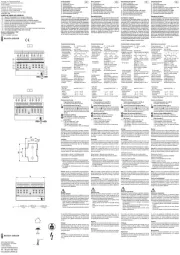
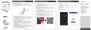
Bedienung
1 = Geräteidentikation während der Inbetriebnahme
2 = Identikations-LED 3 = Busanschlussklemme
4 = Anschlussklemmen
Service
ABB STOTZ-KONTAKT GmbH
Eppelheimer Straße 82, 69123 Heidelberg
Tel. DE 0800 3733 28 4
Tel. CH +41 58 586 07 00
E-Mail: knx.helpline@de.abb.com
www.abb.com/freeathome
BI-M-4.0.1
6241/4.0 Anschluss von Wechselspannung Anschluss von Gleichspannung
English
Binary input, 4gang, MDRC
WARNING
Dangerous currents ow through the body when com-
ing into direct or indirect contact with live components.
This can result in electric shock, burns or even death.
Ø Disconnect the mains power supply prior to installation/
disassembly!
Ø Permit work on the 230 V supply system to be
performed only by specialist staff.
n Please read the mounting instructions carefully and keep them
for future use.
n Additional user information is available at
www.abb.com/freeathome or by scanning the QR code.
n For information on system integration please see the system
manual (www.abb.com/freeathome).
Intended use
The device is suitable for recording of voltages in the range of
10 ... 230 V AC/DC.
n For detailed information about the range of functions see the
technical reference manual (see QR code).
Technical data
Power supply 21 ... 30 V DC
Power loss P Max. 0.1 W
Bus connection Bus connecting terminal, screwless
0-signal
1-signal
0 ... 2 V AC/DC
7 ... 265 V AC/DC
Maximum polling current 355 mA
Inrush current per output
Max. 750 mA at Tu = 60C°
Connecting terminal
Output
Screw terminals
0.2 ... 2.5 mm² ne-wire
0.2 ... 4 mm² single-wire
Protection IP 20 according to EN 60 529
Protection class II according to EN 61 140
Overvoltage category III according to EN 60 664-1
Pollution degree 2 according to EN 60 664-1
Atmospheric pressure Atmosphere up to 2,000 m
Ambient temperature -5 °C – +45 °C
Storage temperature -20 °C – +70 °C
Mounting
Install the device only on mounting rails according to
DIN EN 60715. Remove the stick-on label and glue it into the list
(at System Access Point).
Connection
n The electrical connection is made via screw terminals.
The description of the terminals is found on the housing.
n The connection to the bus line is made via the enclosed bus
connection terminal (red/black).
n To ensure that the glow lamps of illuminated inserts of switches
and push-buttons function correctly and are adequately illumi-
nated, the use of switch or push-button inserts with N-terminals
is absolutely necessary.
Commissioning
The device connected to the busline is automatically recognized by
the system after a few seconds. The devices must be parameter-
ised for the use of the functions.
n Detailed information about commissioning and parameteriza-
tion is available in the technical reference manual and the
online help of the "System Access Point"
(www.abb.com/freeathome).
n Firmware update is carried out via the System Access Point.
Operation
1 = Device identication during commissioning
2 = Identications-LED 3 = Bus connection terminal
4 = Connecting terminals
Service
ABB STOTZ-KONTAKT GmbH
Eppelheimer Straße 82, 69123 Heidelberg, Germany
Tel. +49 2351 956-1600
E-mail: knx.helpline@de.abb.com
www.abb.com/freeathome
Español
Entrada binaria 4 elementos, REG
ADVERTENCIA
En caso de entrar en contacto, directa o indirectamente, con
componentes por los que circule una corriente eléctrica, se
puede sufrir una descarga eléctrica peligrosa, cuyo resultado
puede ser choque eléctrico, quemaduras o, incluso, la muerte.
Ø¡Desconecte la tensión de red antes de proceder al montaje o
desmontaje!
Ø Encargue los trabajos en la red eléctrica de 230 V solo al
personal técnico competente.
n
Lea detenidamente y guarde en lugar seguro el manual de montaje.
n Más información para usuarios en www.abb.com/freeathome o esca-
neando el código QR.
n Para más información sobre la integración en el sistema, consulte el
manual del sistema (www.abb.com/freeathome).
Uso conforme al n previsto
El aparato es adecuado para detectar tensiones dentro del margen de
10 ... 230 V c.a./c.c.
n Si desea información más detallada sobre las funciones, consulte el
manual técnico (véase el código QR).
Datos técnicos
Alimentación de corriente
21 ... 30 V c.c.
Potencia disipada P Máx. 0,1 W
Conexión de bus
Borne de conexión de bus, sin tornillo
Señal 0
Señal 1
0 ... 2 V c.a./c.c.
7 ... 265 V c.a./c.c.
Corriente de detección máx.
355 mA
Corriente de conexión
por salida máx. 750 mA con Tent
= 60 °C
Borne de conexión
Salida
Bornes roscados
0,2 ... 2,5 mm² exible
0,2 ... 4 mm² de un hilo
Tipo de protección IP 20 según EN 60 529
Clase de protección II según EN 61 140
Categoría de sobretensión
III según EN 60 664-1
Grado de contaminación 2 según EN 60 664-1
Presión del aire Atmósfera hasta 2 000 m
Temperatura ambiente -5 °C – +45 °C
Temperatura
de almacenamiento
-20 °C – +70 °C
Montaje
Instale el aparato sobre carriles DIN según la norma EN 60715.
Retire la etiqueta adhesiva y péguela en la lista (en System Access
Point).
Conexión
n La conexión eléctrica se realiza mediante bornes roscados.
Las denominaciones de los bornes se encuentran en la carca-
sa.
n La conexión con la línea de bus se efectúa con el borne de
conexión de bus suministrado (rojo/negro).
n Para garantizar un funcionamiento perfecto y una iluminación
suciente de las lámparas de neón de los mecanismos de inte-
rruptor o pulsador con iluminación, se requiere obligatoriamen-
te el empleo de mecanismos para conmutadores o pulsadores
con borne N.
Puesta en servicio
El sistema reconoce automáticamente tras unos segundos el
aparato que se conecta a la línea de bus. Para la ejecución de las
funciones adicionales es necesario parametrizar los aparatos.
n Podrá encontrar información detallada sobre la puesta en
servicio y sobre la parametrización en el manual técnico y en
la ayuda online del “System Access Point” o punto de acceso
del sistema (www.abb.com/freeathome).
n La actualización del rmware se realiza a través del System
Access Point (punto de acceso del sistema).
Manejo
1 = Identicación de los aparatos durante la puesta en servicio
2 = LED de identicación 3 = Borne de conexión de bus
4 = Borne de conexión
Servicio postventa
ABB STOTZ-KONTAKT GmbH
Eppelheimer Straße 82, 69123 Heidelberg
Tel. +34 902 11 15 11
E-Mail: knx.helpline@de.abb.com
www.abb.com/freeathome
Italiano
Ingresso binario 4x, REG
AVVERTIMENTO
Il contatto diretto o indiretto con parti attraversate da corrente
elettrica provoca pericolosi ussi di corrente attraverso il corpo.
Le conseguenze possono essere folgorazione, ustioni o morte.
ØPrima del montaggio o dello smontaggio scollegare la tensione
di rete!
Ø Afdare gli interventi sulla rete elettrica a 230 V esclusiva-
mente a personale specializzato.
n Leggere e conservare con cura le istruzioni per il montaggio.
n Maggiori informazioni per l'utente disponibili sul sito
www.abb.com/freeathome o tramite scansione del codice QR.
n Per informazioni sull'integrazione nel sistema vedere il manuale del
sistema (www.abb.com/freeathome).
Uso conforme alle prescrizioni
L'apparecchio si presta al rilevamento di tensioni in un intervallo di
10 ... 230 V AC/DC.
n Per informazioni dettagliate sulle funzioni disponibili consultare il
manuale tecnico (vedere il codice QR).
Dati tecnici
Alimentazione elettrica 21 ... 30 V DC
Potenza dissipata P Massimo 0,1 W
Collegamento bus
Morsetto di allacciamento bus, senza viti
Segnale 0
Segnale 1
0 ... 2 V AC/DC
7 ... 265 V AC/DC
Corrente
di interrogazione max
355 mA
Corrente di inserzione
per ogni uscita max 750 mA con T
u = 60 C°
Morsetto
Uscita
Morsetti a vite
0,2 ... 2,5 mm² a lo ne
0,2 ... 4 mm² monolo
Tipo di protezione IP 20 a norma EN 60 529
Classe di protezione II A norma EN 61 140
Categoria di sovratensionesione
III a norma EN 60 664-1
Grado di sporcizia 2 a norma EN 60 664-1
Pressione aria Atmosfera no a 2.000 m
Temperatura ambiente - 5 °C – + 45 °C
Temperatura
di immagazzinamento
- 20 °C – + 70 °C
Montaggio
Installare l'apparecchio esclusivamente su guide DIN conformi a
DIN EN 60715. Staccare l'etichetta adesiva e incollarla nella lista
(per System Access Point).
Collegamento
n Il collegamento elettrico è realizzato tramite morsetti a vite.
I codici dei morsetti sono riportati sulla scatola.
n Il collegamento alla linea bus è realizzato tramite il morsetto
bus allegato (rosso/nero).
n Per un funzionamento perfetto e un'illuminazione sufciente
delle lampade uorescenti degli interruttori o di moduli pulsante
illuminati è assolutamente richiesto l'utilizzo di interruttori o
moduli pulsante dotati di morsetto N.
Messa in funzione
L'apparecchio collegato alla linea bus viene rilevato automatica-
mente dal sistema dopo alcuni secondi. Per utilizzare le funzioni è
necessario parametrizzare gli apparecchi.
n Per informazioni dettagliate sulla messa in servizio e sulla pa-
rametrizzazione consultare il manuale tecnico o la guida online
del "System Access Point" (www.abb.com/freeathome).
n L'aggiornamento rmware avviene tramite System Access
Point.
Uso
1 = identicazione dell'apparecchio durante la messa in servizio
2 = LED identicativo 3 = Morsetto di allacciamento bus
4 = Morsetti
Service
ABB STOTZ-KONTAKT GmbH
Eppelheimer Straße 82, D-69123 Heidelberg
Tel. IT 0800 55 1166
Tel. CH +41 58 586 07 00
E-Mail: knx.helpline@de.abb.com
www.abb.com/freeathome
www.abb.com/freeathome
www.busch-jaeger.de/freeathome
IP20 -5 °C
+45 °C
IP20 -5 °C
+45 °C
IP20 -5 °C
+45 °C
IP20 -5 °C
+45 °C