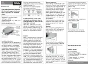
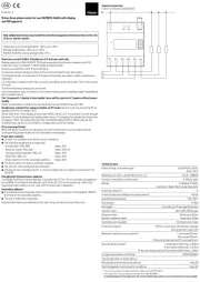
Module to control a relay contact over the
DALI bus (DT7) for DIN top-hat rails DIN-EN
60715 TH35. 98x17,5x56 mm. Protection
class IP20. DALI current consumption 2.7 mA.
Compact relay module for direct control of
230 V loads over DALI. Loads without DALI
input are easily integrated in a DALI circuit.
Loads can be switched on/off by DALI com-
mands. The device function complies with
the standard for DALI Device Type 7 – switching
function (as of Firmware 2.0). Adjustable
characteristic for power-up and bus power
The DALI RM16 is powered over the DALI bus.
No additional power supply is required.
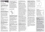
Zero passage switch-on. Integrated power-
on current limit, particularly suitable for
loads with very high power-on current
(> 100 A). The interface represents a bus
user and is therefore addressable.
Conguration via DALI Cockpit PC software.
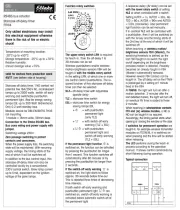
DALI functions and command set:
The DALI RM16 can integrate loads on the
DALI bus and can then switch them on/off.
The DALI RM16 is a control device for non-
dimmable loads based on the DALI speci-
cations in IEC 62386-208 (Device Type 7).
Accordingly, the switch characteristic is
determined by comparing the virtual dim
level (VDAP) with 4 switching thresholds.
The virtual dim level (VDAP) corresponds to
the dim level of a DALI electronic ballast with
Temperature at mounting location:
Storage temperature: -25°C up to +70°C.
annual average value <75%.
Only skilled electricians may install this
electrical equipment otherwise there is
the risk of re or electric shock!
its corresponding characteristics (limited
by MINLEVEL and MAXLEVEL, dimming
speed limited by fade time and fade rate).
There are 2 switching thresholds in each
dimming direction and they are used for
comparison with the virtual dim level. Only
the applicable switching threshold for the
current virtual dimming direction is evaluated.
A threshold with the value 'MASK' is inactive
and is not used in the comparison.
Switch-on/off delays can be implemented
The DALI RM16 is powered from the DALI bus.
The relay response to a bus power failure can
be congured by the SystemFailureLevel
(no change, ON or OFF, factory setting: ON).
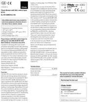
The power-on response after applying bus
power can be set with PowerOnLevel.
Max. connected current 16 A
Must be kept for later use!
Technical Support English:
technical-support@eltako.de
05/2022 Subject to change without notice.
The crossed-out waste container indicates
that batteries may not be disposed with
other household or commercial waste.