Extron DVI DA Plus Series Manual

Extron Modtager DVI DA Plus Series

Læs gratis den danske manual til Extron DVI DA Plus Series (2 sider) i kategorien Modtager. Denne vejledning er vurderet som hjælpsom af 26 personer og har en gennemsnitlig bedømmelse på 4.4 stjerner ud af 13.5 anmeldelser. Har du et spørgsmål om Extron DVI DA Plus Series, eller vil du spørge andre brugere om produktet?

Side 1/2
1
Product Category
DVI DA Plus Series • Setup Guide
Overview
These instructions provide a quick setup guide for the Extron DVI DA Plus Series distribution amplifiers. Installation and
service must be performed only by experienced installers. More complete instructions can be found in the DVI DA Plus Series
User Guide, which can be found online at www.extron.com.
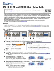
Installation
Mounting
Install the distribution amplifier on a desk, under a desk, or in a rack.
DVI Cable Connections
A typical application is shown in the figure at right. Connect these
cables, but do not power on the equipment yet:
zConnect a DVI cable from the Input connector to the video
source device.
zConnect aDVI cables from the distribution amplifier to the
desired display devices.
Power Cable Connections
Connect the 12 VDC power supply to the power receptacle of the unit. The figure below shows the 1 A power supply for the
DVI DA4 Plus. The DVI DA6 Plus and DVI DA8 Plus require a 3 A power supply.
CAUTION: See the Caution in the “Power Input” section of
the DVI DA Plus Series User Guide, for important
information about power supplies.
NOTES: • Thelengthoftheexposedwiresinthestrippingprocess
is critical. The ideal length is 3/16 inches (5 mm). If the
exposed section is longer, the exposed wires may touch,
causing a short circuit between them. If it is shorter, the
wires can be easily pulled out even if tightly fastened by
the captive screws.
• Donottinthewires.Tinnedwiredoesnotholditsshape
and can become loose over time.
Applying Power
In the following order:
1. Power on the display devices.
2. Power on the distribution amplifier.
3. Power on the source input device.
EDID Minder®
The Extron EDID Minder feature maintains continuous EDID (Extended Display Identification Data) communication with
the attached source and ensures that the DVI source powers up correctly and maintains a proper video output, even if the
display is off or when a new monitor is connected to the output.
When the distribution amplifier is powered on, it automatically scans all detectable outputs, selects the device with the
lowest native resolution and passes the EDID information of that device to the input device. If no output displays are
connected, the distribution amplifier provides the EDID information stored from the last display to which it was connected.
If no output device has previously been connected to the unit, or the unit has been set to the factory default, it uses the
factory default resolution (1024x768 @ 60 Hz).
12V
0.4A MAX
POWER
DVI-D INPUT DVI-D OUTPUT
1 2 3 4 5 6 7 8
DVI DA8 Pl us
Computer
with
DVI O tutpu
Local
Monitor
Display
with
DVI Input
Display
with
DVI Input
Extron
DV 8 I DA Plus
Distribution A rmplie
12V
1.0A MAX
POWER
Back Panel
Power Receptacle
DC wer Cord Po
Captive Screw Connector
AC Power Cord
Ground
+12 VDC
Exte al rn
Power Supply
(12 VD 1 A C,
)
2
DVI DA Plus Series • Setup Guide (Cont’d)
Part Number EDID Minder
Inactivation
DIP Switches
EDID Lo andck
Pre-emphasis
DIP Switches
Rear Panel
DVI DA4 Plus
Disabling the EDID Minder
Some applications require that the EDID Minder feature is disabled for specific outputs or are ignored during the automatic
scanning process. To prevent EDID being read from specific outputs:
1. Remove and keep the screws holding the cover to the base (seven screws for the DVI DA4 Plus, ten screws for the
DVI DA6 Plus and DVI DA8 Plus). Save the screws and set aside the cover.
2. Check the part number of the printed circuit board (outlined in the figure above left). The boards must have a part
number of 20-1496-01LF and higher (DVI DA4 Plus) or 20-1497-01LF and higher (DVI DA6 Plus or DVI DA8 Plus).
NOTE: If the part number of the board is lower than these values, you cannot deactivate the EDID Minder on your
model. Replace the cover as described in step 5.
3. Locate the EDID Minder Inactivation DIP switches. The DVI DA4 Plus has a single bank of four switches (see the figure
above left). Each switch regulates the correspondingly numbered output (1-4).
The DVI DA6 Plus and DVI DA8 Plus have two banks of four switches (see the figure above right). In bank 1, each switch
regulates the correspondingly numbered output (1-4). In bank 2, switches 1 and 2 correspond to outputs 5 and 6 for the
DVI DA6 Plus; switches 1-4 correspond to outputs 5-8 for the DVI DA8 Plus.
4. By default the switches are in the off/down position, allowing the EDID information to be read from the corresponding
output. To deactivate EDID Minder for one or more outputs, move the switch for that output to the on/up position.
5. Replace the cover, using the screws that were removed in step 1.
EDID Lock and Pre-emphasis
By default, EDID information stored at the input is lost when the unit goes through a power cycle or a new output display is
connected to the device. EDID Lock maintains specific EDID information so that it is not lost after these events.
Pre-emphasis compensates for poor signals delivered to output devices.
To enable EDID Lock or Pre-emphasis:
1. Remove the cover and locate the part numbers as described in steps 1 and 2 of the previous section.
2. Locate the EDID Lock and Pre-emphasis DIP switches (outlined in the figure above left). For all three models, the
EDID Lock DIP switch is labeled EDID Mode; the Pre-emphasis DIP switch is labeled Preemph.
3. By default, the EDID Mode and Pre-emphasis DIP switches are in the down (disabled) position. To enable either feature,
toggle the appropriate switch to the up position.
NOTE: Before enabling the EDID Lock feature, be sure the desired EDID is currently being used.
4. Replace the cover, using the screws that were removed in step 1.
Extron USA - West
Headquarters
+800.633.9876
Inside USA/Canada Only
+1.714.491.1500
+1.714.491.1517 FAX
Extron USA - East
+800.633.9876
Inside USA/Canada Only
+1.919.863.1794
+1.919.863.1797 FAX
Extron Europe
+800.3987.6673
Inside Europe Only
+31.33.453.4040
+31.33.453.4050 FAX
Extron Asia
+800.7339.8766
Inside Asia Only
+65.6383.4400
+65.6383.4664 FAX
Extron Japan
+81.3.3511.7655
+81.3.3511.7656 FAX
Extron China
+400.883.1568
Inside China Only
+86.21.3760.1568
+86.21.3760.1566 FAX
Extron Middle East
+971.4.2991800
+971.4.2991880 FAX
© 2011 Extron Electronics All rights reserved. www.extron.com
68-1536-50 Rev. C
02 11
EDID Disable DIP Switches for I DA6 (shown) and DVI 8DV DA
Bank 1:
Outputs 1-4
Bank 2:
Outputs 5-6 (DVI 6 Plus)DA
Outputs 5-8 (DVI 8 Plus)DA


Produkt Specifikationer

Mærke: Extron
Kategori: Modtager
Model: DVI DA Plus Series

Har du brug for hjælp?

Hvis du har brug for hjælp til Extron DVI DA Plus Series stil et spørgsmål nedenfor, og andre brugere vil svare dig