- La sicurezza dell’apparecchio è garantita solo con l’adozione delle istruzioni di sicu-
rezza e di utilizzo; pertanto è necessario conservarle. Assicurarsi che queste istruzio-
ni siano ricevute dall’installatore e dall’utente finale.
- Questo prodotto dovrà essere destinato solo all’uso per il quale è stato espressamen-
te concepito. Ogni altro uso è da considerarsi improprio e/o pericoloso. In caso di
dubbio contattare il SAT Servizio Assistenza Tecnica GEWISS.
- Il prodotto non deve essere modificato. Qualsiasi modifica annulla la garanzia e può
rendere pericoloso il prodotto.
- Il costruttore non può essere considerato responsabile per eventuali danni derivati da
usi impropri, erronei e manomissioni del prodotto acquistato.
- Punto di contatto indicato in adempimento ai fini delle direttive e regolamenti UE
GEWISS S.p.a. Via A. Volta, 1 - 24069 Cenate Sotto (BG) - Italy
Tel.: +39 035 946 111 - qualitymarks@gewiss.com
Il simbolo del cassonetto barrato, ove riportato sull’apparecchiatura o
sulla confezione, indica che il prodotto alla fine della propria vita utile deve
essere raccolto separatamente dagli altri rifiuti. AI termine dell’utilizzo,
l’utente dovrà farsi carico di conferire il prodotto ad un idoneo centro di
raccolta dierenziata oppure di riconsegnarlo al rivenditore all’atto
dell’acquisto di un nuovo prodotto. Presso i rivenditori con superficie di vendita di al-
meno 400 m² è possibile consegnare gratuitamente, senza obbligo di acquisto, i
prodotti da smaltire con dimensioni inferiori a 25 cm. L’adeguata raccolta dierenziata
per l’avvio successivo dell’apparecchiatura dimessa al riciclaggio, al trattamento e allo
smaltimento ambientalmente compatibile contribuisce ad evitare possibili eetti nega-
tivi sull’ambiente e sulla salute e favorisce il reimpiego e/o riciclo dei materiali di cui è
composta l’apparecchiatura. GEWISS partecipa attivamente alle operazioni che favori-
scono il corretto reimpiego, riciclaggio e recupero delle apparecchiature elettriche ed
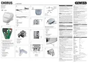
CONTENUTO DELLA CONFEZIONE
La confezione di fornitura del sensore di luminosità KNX contiene i seguenti com-
N.1 Dispositivo sensore di luminosità KNX
N.1 Manuale di installazione
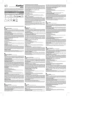
Il sensore di luminosità misura l’intensità dell’illuminazione e trasferisce il valore
Dispone di 6 oggetti di comunicazione in uscita di tipo on/off associabili a soglie
impostabili e di porte logiche AND/OR addizionali.
Nell’involucro del dispositivo è alloggiato il sensore e l’elettronica per il collega-
mento del bus KNX (figura A).
• Rilevazione luminosità:
l’intensità luminosa è misurata tramite il relativo sensore.
• Uscite di commutazione:
3 oggetti di comunicazione di tipo on/off per funzione crepuscolare (fino a 1000
lux) e 3 per funzione di sensore luminosità (1-99 Klux), associabili a soglie impo-
stabili (i valori di soglia possono essere impostati attraverso parametri o tramite
oggetti di comunicazione).
sono disponibili 8 porte AND e 8 porte OR, ciascuna delle quali supporta un
massimo di quattro ingressi. I valori delle uscite di commutazione associate alle
funzioni crepuscolare e di sensore luminosità possono essere utilizzati diretta-
mente come ingressi logici. L’uscita di ciascuna porta logica può generare l’invio
di un oggetto di comunicazione da 1bit o due oggetti da 1byte.
ATTENZIONE: l’installazione del dispositivo deve essere effettuata
esclusivamente da personale qualificato, seguendo la normativa vi-
gente e le linee guida per le installazioni KNX/EIB.
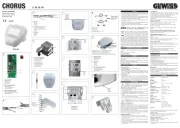
AVVERTENZE PER L’INSTALLAZIONE KNX/EIB
1. La lunghezza della linea bus tra il sensore di luminosità KNX e l’alimentatore
non deve superare i 350 metri.
2. La lunghezza della linea bus tra il sensore di luminosità KNX e il più lontano
dispositivo KNX/EIB da comandare non deve superare i 700 metri.
3. Per evitare segnali e sovratensioni non voluti, non dar vita se possibile a circuiti
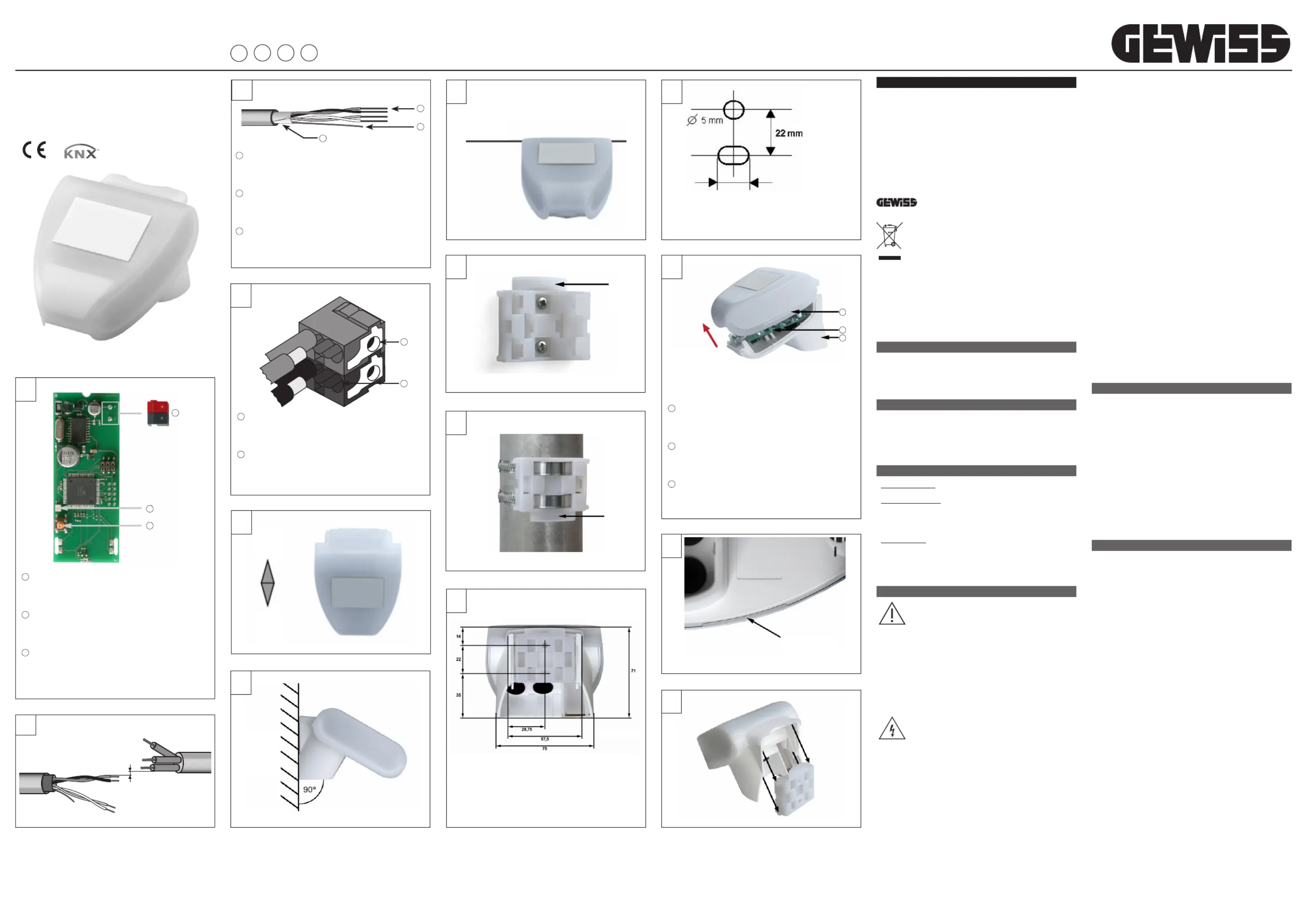
4. Mantenere una distanza di almeno 4 mm tra i cavi singolarmente isolati della
linea bus e quelli della linea elettrica (figura B).
5. Non danneggiare il conduttore di continuità elettrica della schermatura (figura C).
ATTENZIONE: i cavi di segnale del bus non utilizzati e il conduttore di
continuità elettrica non devono mai toccare elementi sotto tensione o
AVVERTENZE PER L’INSTALLAZIONE
L’installazione, l’ispezione, la messa in funzione e l’individuazione/risoluzione di
guasti del sensore di luminosità devono essere eseguiti solo da personale qualificato.
Il dispositivo è concepito esclusivamente per un uso appropriato, qualsiasi mo-
difica non appropriata o la non osservanza delle istruzioni d’uso renderà nulla la
garanzia e qualsivoglia reclamo non avrà valore.
Il sensore di luminosità deve essere azionato solamente dopo essere stato corret-
tamente montato e dopo il completamento di tutte le operazioni di installazione e
di start-up e solo nell’ambiente previsto per il suo utilizzo.
Per gli schemi di connessione elettriche si vedano gli esempi che seguono.
1. Connettere il filo rosso del cavo bus al morsetto rosso (+) del terminale e il filo
nero al morsetto nero (-).
Al terminale bus si possono collegare fino a 4 linee bus (fili dello stesso colore
nello stesso morsetto) (figura D).
2. Isolare lo schermo, il conduttore di continuità elettrica e i rimanenti fili bianco
e giallo del cavo bus (nel caso in cui si utilizzi un cavo bus a 4 conduttori), che
Per il montaggio scegliere un’ubicazione in cui il sensore di luminosità sia in grado
di rilevare la luce solare senza alcun impedimento. Il sensore non deve essere
ombreggiato dall’edificio o da altri ostacoli quali, ad esempio, da alberi.
Allineare il sensore di luminosità in direzione sud. (figura E)
Il sensore di luminosità deve essere montato in posizione verticale su un muro o
Il sensore di luminosità deve essere montato in posizione orizzontale. (figura G)
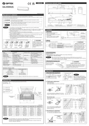
Il sensore di luminosità viene fornito con un supporto da parete o da palo.
Fissare il supporto verticalmente su di una parete o un palo.
Montaggio a parete: parte piatta sulla parete, parte con collarino sporgente
rivolta verso l’alto. (figura H)
Montaggio su di un palo: parte curva sul palo, collarino rivolto verso il basso.
VISTA DELLA PARTE POSTERIORE E SCHEMA DI FORATURA (figura L)
Dimensioni della parte posteriore dell’alloggiamento con staffa (figura M).
Soggetta a modifiche in caso di migliorie.
PREDISPOSIZIONE DEL SENSORE (figura N)
Il coperchio del dispositivo è dotato di innesti a sinistra e a destra lungo il bordo
Spingere il cavo per la connessione bus attraverso la guarnizione di gomma sul
fondo del sensore e collegare il bus KNX agli appositi morsetti.
Chiudere l’alloggiamento ricollocando il coperchio sulla parte inferiore.
Il coperchio deve innestarsi perfettamente a destra e a sinistra, udendo un nitido
Accertarsi che il coperchio e la parte inferiore siano effettivamente bloccati
Questa figura mostra il sensore chiuso con vista dal basso. (figura O)
Spingere l’alloggiamento da sopra nel supporto fissato.
Le protuberanze presenti sul supporto devono innestarsi a scatto nelle guide
dell’alloggiamento. (figura P)
Il programma applicativo può essere scaricato dal sito www.gewiss.com. Infor-
mazioni dettagliate sui parametri di configurazione e sui loro valori sono contenuti
PROGRAMMAZIONE INDIRIZZO FISICO
1. Alimentare il dispositivo attraverso il bus.
2. Premere il pulsante di programmazione per predisporre il sensore di luminosità
KNX al caricamento da ETS dell’indirizzo fisico.
Per poter configurare il dispositivo via ETS è sufficiente l’alimentazione bus KNX.
Il sensore deve essere controllato regolarmente due volte l’anno per individuare
un’eventuale presenza di sporcizia e se necessario deve essere pulito.
Per rimuovere il sensore è sufficiente tirare semplicemente verso l’alto, vincendo
la resistenza del fissaggio.
Non aprire il sensore in caso di pioggia o comunque se dell’acqua può penetrare
all’interno: anche poche gocce possono danneggiare il sistema elettronico.
Contenitore: materiale plastico
Grado di protezione: IP44
Dimensioni: 96 × 77 × 118 (L × H × P, mm)
funzionamento e stoccaggio:
Alimentazione: tensione bus KNX
Assorbimento bus KNX: max. 10 mA, con ripple 10%
Connettore dati uscita: standard KNX
BCU tipo: inclusa nel microcontrollore
Indirizzi di gruppo: max. 254
Oggetti di comunicazione: 117
Range sensore di luminosità: 0…150000 lux
Risoluzione: 1 lux a 0…120 lux
423 lux a 52364…150000lux
I seguenti standard sono stati presi in considerazione per la valutazione del prodot-
to in termini di compatibilità elettromagnetica:
• EN 60730-1:2000 Sezione EMC (23, 26, H23, H26) (categoria soglia: B)
• EN 50090-2-2:1996-11 + A1:2002-01 (categoria soglia: B)
• EN 61000-6-3:2001 (categoria soglia: B)
Resistenza alle interferenze:
• EN 60730-1:2000 Sezione EMC (23, 26, H23, H26)
• EN 50090-2-2:1996-11 + A1:2002-01
Il prodotto è stato testato a fronte degli standard sopracitati da un laboratorio
LED di programmazione KNX
Pulsante di programmazione KNX
KNX push-button for programming
Bouton-poussoir de programmation KNX
Conduttore di continuità elettrica
Electrical continuity conductor
Conducteur de continuité électrique
Connessione dispositivo bus
Connection of the BUS device
Connection of the BUS cable
KNX light intensity sensor
Capteur de luminosité KNX
Verschließbare Önung 7,5 x 5 mm
Parte inferiore dell’alloggiamento
Lower part of the housing
Partie inférieure du logement
Sganciare il coperchio e rimuoverlo tirando verso l’alto
Unhook the cover and remove it by pulling upwards
Décrocher le couvercle et le retirer en tirant vers le haut
Den Deckel aushängen und entfernen, indem man ihn nach unten zieht