I-PRO WV-QCL500-S Manual
I-PRO
Ikke kategoriseret
WV-QCL500-S
| Mærke: | I-PRO |
| Kategori: | Ikke kategoriseret |
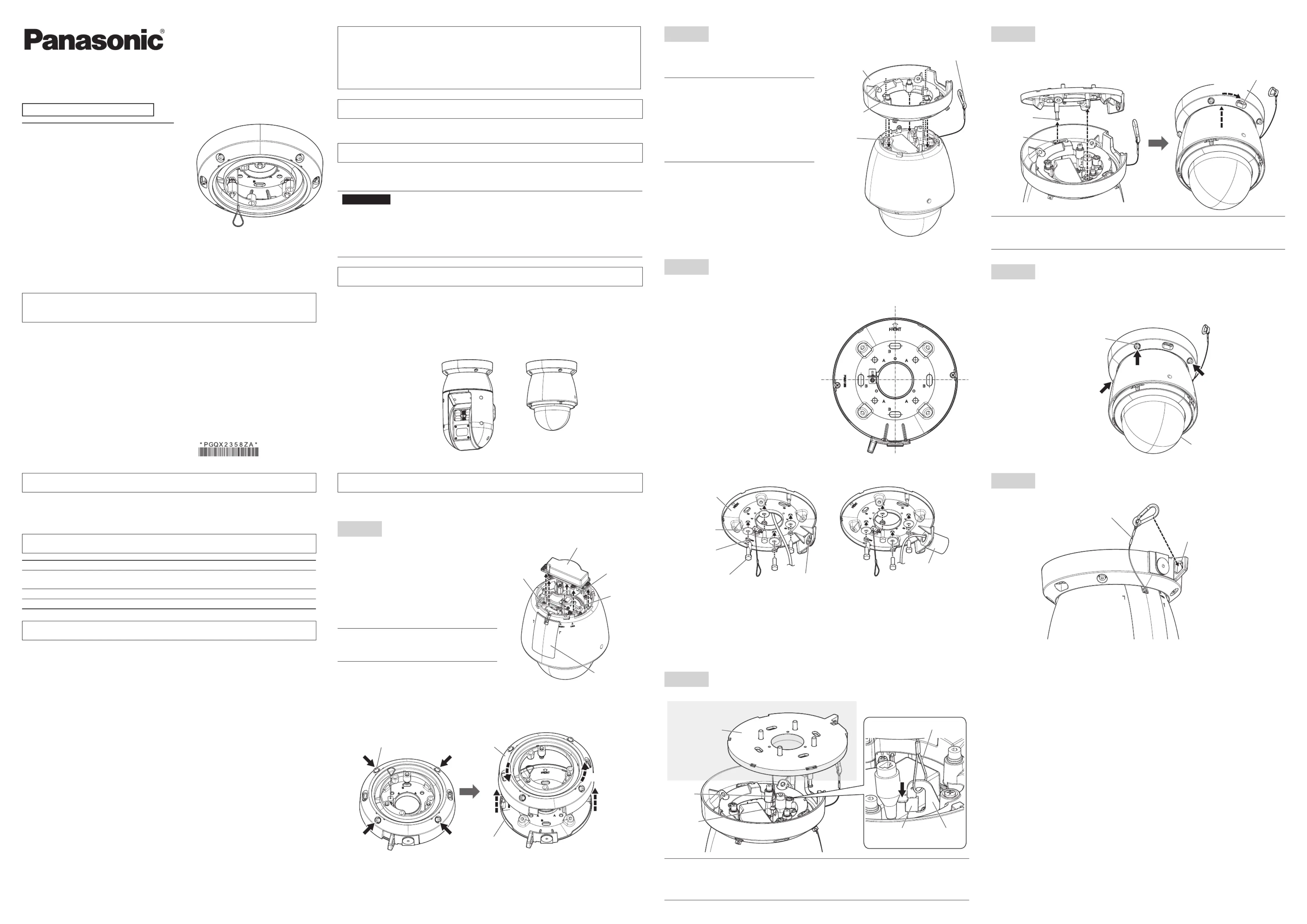
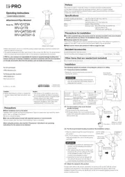
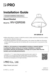
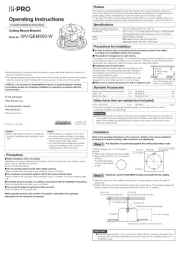
| Model: | WV-QCL500-S |
| Type: | Loftmonteringsfod |
| Antal pr. pakke: | 1 stk |
| Produktfarve: | Sølv |
Har du brug for hjælp?
Hvis du har brug for hjælp til I-PRO WV-QCL500-S stil et spørgsmål nedenfor, og andre brugere vil svare dig
Ikke kategoriseret I-PRO Manualer
9 Oktober 2025

7 Oktober 2025
29 September 2025
18 Juli 2025
17 Juli 2025

17 Juli 2025
16 Juli 2025

15 Juli 2025

14 Juli 2025
27 Marts 2025
Ikke kategoriseret Manualer
- Excalibur
- Bayco
- Itho-Daalderop
- XM
- Geeni
- Rupert Neve Designs
- Peavey
- Redragon
- Copper Creek
- McIntosh
- Telmax
- Nevadent
- Hosa
- Keith MCmillen
- Mazzer
Nyeste Ikke kategoriseret Manualer

18 December 2025

18 December 2025

18 December 2025

18 December 2025

18 December 2025

18 December 2025

18 December 2025

18 December 2025

18 December 2025

18 December 2025