I-PRO WV-QWL500-W Manual
I-PRO
Ikke kategoriseret
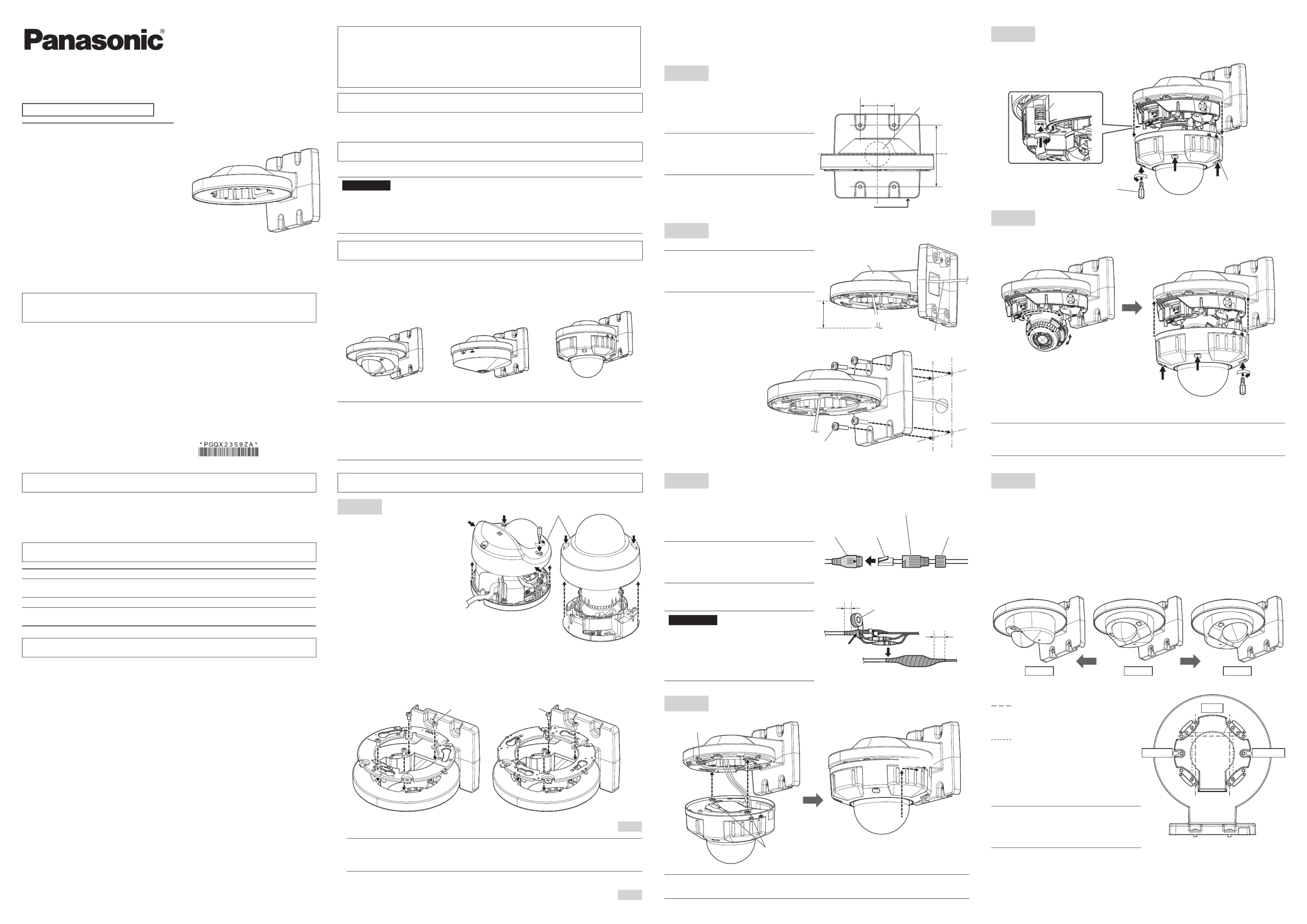
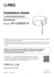
WV-QWL500-W
| Mærke: | I-PRO |
| Kategori: | Ikke kategoriseret |
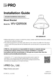
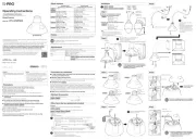
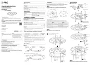
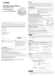
| Model: | WV-QWL500-W |
| Type: | Montering |
| Bredde: | 158 mm |
| Dybde: | 188 mm |
| Højde: | 112 mm |
| Vægt: | 520 g |
| Produktfarve: | Hvid |
| Driftstemperatur (T-T): | -50 - 60 °C |
| Husmateriale: | Aluminium |
| Understøttet placering: | Universel |
Har du brug for hjælp?
Hvis du har brug for hjælp til I-PRO WV-QWL500-W stil et spørgsmål nedenfor, og andre brugere vil svare dig
Ikke kategoriseret I-PRO Manualer
9 Oktober 2025
7 Oktober 2025
29 September 2025
18 Juli 2025
17 Juli 2025
17 Juli 2025
16 Juli 2025
15 Juli 2025
14 Juli 2025
27 Marts 2025
Ikke kategoriseret Manualer
- Bēm Wireless
- 8BitDo
- GFM
- Akrobat
- KM-fit
- Nerf
- Apple
- MilanToast
- Real Cable
- Robbe
- AUTOUTLET
- Swingline
- Bialetti
- Sauber
- Manley
Nyeste Ikke kategoriseret Manualer

17 December 2025

17 December 2025

17 December 2025

17 December 2025

17 December 2025

17 December 2025

17 December 2025

17 December 2025

17 December 2025

17 December 2025