I-PRO WV-QJB503 Manual
I-PRO
Ikke kategoriseret
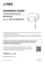
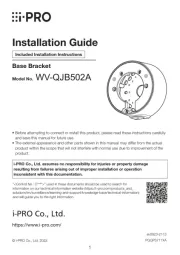
WV-QJB503
| Mærke: | I-PRO |
| Kategori: | Ikke kategoriseret |
| Model: | WV-QJB503 |
Har du brug for hjælp?
Hvis du har brug for hjælp til I-PRO WV-QJB503 stil et spørgsmål nedenfor, og andre brugere vil svare dig
Ikke kategoriseret I-PRO Manualer
9 Oktober 2025
7 Oktober 2025
29 September 2025
18 Juli 2025
17 Juli 2025
17 Juli 2025
16 Juli 2025
15 Juli 2025
14 Juli 2025
27 Marts 2025
Ikke kategoriseret Manualer
- Testec
- Radionette
- Eowave
- Irradio
- Watercool
- Imation
- Melinera
- Profilo
- COMSOON
- Newline
- Gardebruk
- Sherwood
- Gustard
- ABB
- Mybeo
Nyeste Ikke kategoriseret Manualer
4 November 2025
4 November 2025
4 November 2025
4 November 2025
4 November 2025

4 November 2025
4 November 2025
4 November 2025

4 November 2025

4 November 2025