JobSite IR-FMR Manual

JobSite Modtager IR-FMR

Læs gratis den danske manual til JobSite IR-FMR (2 sider) i kategorien Modtager. Denne vejledning er vurderet som hjælpsom af 3 personer og har en gennemsnitlig bedømmelse på 4.9 stjerner ud af 2 anmeldelser. Har du et spørgsmål om JobSite IR-FMR, eller vil du spørge andre brugere om produktet?

Side 1/2
1 452 3 6
Over Please
PACKAGE CONTENTS
n IR-FMR Receiver x 1
n White Bezel x 1
n Black Bezel x 1
n Washer x 1
n Hex Nut x 1
PREPARING FOR INSTALLATION
The IR-FMR Receiver cable must reach the
proposed location of the IR Connecting Block. If
not, use Category 5 cable to extend the length.
Mark the cable with a Wire label, describing where
the cable originates from, rather than where it will
terminate. Verify there are 3 inches of clearance
behind the surface where you plan to mount the
IR-FMR.
TOOLS REQUIRED
n 1/8" Slotted screwdriver
n Adjustable wrench or pliers
n Wire stripper
n Wire labels
INSTALLATION
1. Determine a mounting location for the IR-FMR.
2. Drill a 1/2" hole where the IR-FMR will be
mounted.
3. Secure the IR-FMR by tightening the hex nut.
DO NOT OVER-TIGHTEN.
4. Run the IR-FMR cable. Label the cable for future
reference.
5. Strip 1/4" of insulation from the end of each
CAT5 wire.
6. Locate the IR Connecting Block Snap and Lock
Connectors and remove them if they are
plugged in.
7. Use a small flathead screwdriver or your thumb
to raise the locking tabs, exposing the holes on
the connectors.
8. Insert each wire into the appropriate hole and
snap down the locking tabs. See Figure 3.
9. Insert the smooth side
of the connector plug
into the smooth side
of the IR Connecting
Block socket.
See installation diagram.
Installation Note:
The talkback LED can be disabled if it continues to
flicker or visual feedback is not desired. Discrete
on and off IR commands are available on the
JobSite Technical support website for disabling
the flashback LED. The address is:
www.jobsitesystems.com/techsupport/.
Using the IR-FMR with a
JobSite M-4KP Keypad:
The IR-FMR is fully compatible with the JobSite
M-4KP Keypad: follow the wiring instructions in
Figure 4.
Changing the Color of the
IR-FMR:
The bezel surrounding the lens on the IR-FMR is
removable, allowing fast and easy color changes
as needed. Black and white bezels are included
with your IR-FMR.
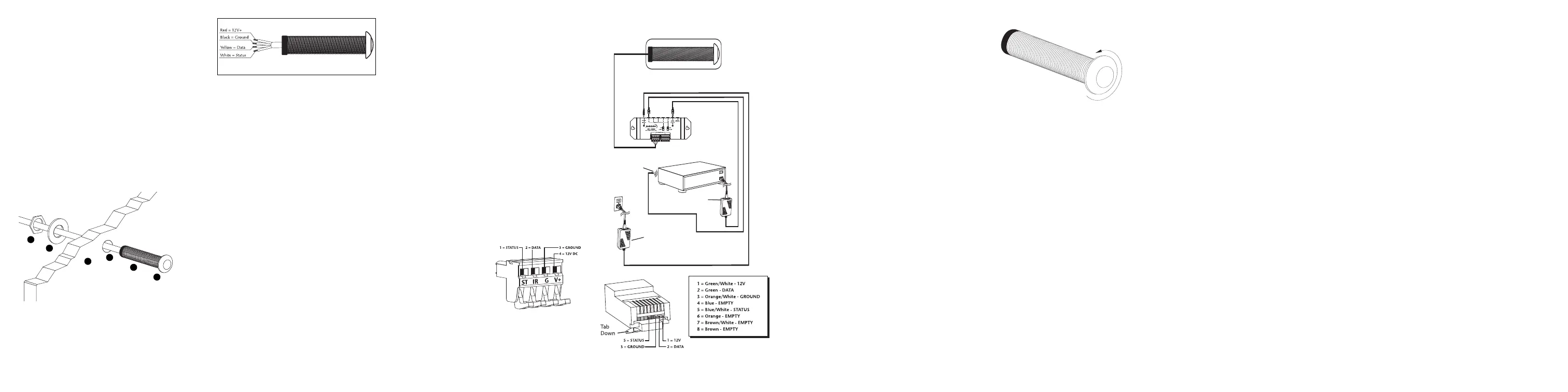
To change the bezel of the
IR-FMR:
1. Hold the IR-FMR so that the front of it is facing
you. Unscrew the bezel by turning it counter-
clockwise as shown in Figure 5.
Note: The IR-FMR’s lens is held in place by the
bezel—be careful not to lose it.
2. Hold the IR-FMR so that the front of it is facing
you, making sure that the lens is in place. Screw
the new bezel onto the IR-FMR by turning it
clockwise.
(Do Not Over Tighten)
OPERATION
Operation of the IR-FMR is simple. Stand within
the operational range of your IR-FMR. Aim your
hand-held remote at the IR-FMR and press the
button for the desired command. Your IR
command is instantly repeated to your A/V
equipment.
Green “Power Status” LED
When the IR-FMR is correctly connected (as
shown in Figure 3, the Green LED will stay lit as
long as the preamp/receiver is on. When your
preamp/receiver is off, the LED will stay off.
Blue “Talkback” LED
The blue “talkback” LED on the IR-FMR visually
confirms the reception of an IR command.
78
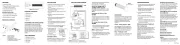
Figure 2 : Wiring legend
a Hex Nut (supplied)
b Washer (supplied)
c Mounting Surface
d IR Cable (10 feet supplied)
e IR-FMR Miniature IR Sensor (supplied)
f IR-FMR Lens Bezel (supplied)
a
b
d
e
f
c
Figure 1
FEATURES
n Plasma-proof design
n Rejects interference from flat panel displays,
CFL lighting or indirect sunlight
n Works with practicality all remotes
n Extended receiving range
Installation friendly design:
n 10' feet of connecting wire included
n Flush mounts into a 1/2" diameter hole
n Black and white bezels included
PRODUCT OVERVIEW
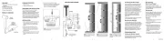
Figure 4 : Suggested wiring of IR-FMR to a RJ45
connector for connection to a JobSite M-4KP keypad.
Stereo Receiver
12V DC Power Supply
(Not Supplied) plugged into
the Switched Outlet
12V DC Power Supply
Plugged into an Unswitched
AC Outlet Powers the
System
IR-CB2
JobSite
IR-E1
Emitter
IR-FMR
Figure 5
Removing the Bezel
TROUBLESHOOTING
1. Test the remote control(s) by operating the A/V
equipment directly. Replace the batteries if
needed.
2. Double-check the cable connections on all
IR-FMRs and on the Connecting Block. Look
for open, shorted or reversed wires.
3. Test for interference from the following
sources:
n Neon or halogen lights in the room
n Light dimmers, beginning with those closest to
the IR-FMR
n Observe the IR-FMR’s LED while performing
all the tests. It is possible to have interference
from more than one source
Eliminating optical feedback:
Optical Feedback Loop:
If you have an IR Receiver in the same room as a
Emitter, and you have some low-level noise or
interference, an optical feedback loop can occur
which will interfere with proper operation.
Symptoms can include: poor range, intermittent
operation or no operation.
Solution:
Replace the IR-E1HO “flooding Emitter” with
IR-E1 or IR-E2 Emitters and covering all Emitters
with the supplied IR Blocking Covers.
Identifying the type of interference:
The “talk-back” LED on the front of the IR-FMR is
a useful trouble-shooting aid. The LED should
light blue only when a remote command is being
received. However, if the LED on the IR-FMR
“flickers”, and the IR-FMR functions normally,
there is no cause for concern.
If the IR-FMR does not work, and the LED
does not light at all:
Test the remote control(s) by operating the A/V
equipment directly. Replace the batteries if
needed. Double-check the wiring connections of
the IR-FMR, at the IR Connecting Block. Consult
your IR Connecting Block’s manual for more
detail.
If the IR-FMR does not work, and the LED
flickers or remains solidly lit:
Cover up the Receiver with a piece of cardboard
(your hand will actually create electromagnetic
interference under some conditions). Observe
the IR test LED.
IR Test LED Off:
Optical Interference.
IR Test LED On or Flickering:
Electromagnetic Interference.
EMI (Electromagnetic Interference):
Solution:
1. Move the Receiver or the Receiver cable away
from the EMI source or move the source of the
EMI away from the Receiver or the cable.
Figure 3
INSTALLATION DIAGRAM
910 1211
INSTALLATION & USER GUIDE
For Receiving and Routing
Infrared Commands from
Any Remote Control
IR-FMR
PLASMA-PROOF MOUNT
IR RECEIVER
2. Connect the Receiver’s GND terminal to true
earth ground (if this isn’t feasible use the
Connecting Block’s GND terminal).
There are many methods for reducing
interference. Which solution is best for you
depends on your situation. If you require further
assistance contact JobSite Technical Support at
1-866-452-7483.
SPECIFICATIONS
IR system
Works with practically all brands of
IR Remote Controls
IR receiving (varies by brand of remote
control):
Range18'-30'
From 20 to 30 degrees off-axis
Wiring requirements
Category 5 or better, Home runs required.
Mounting
1/2" diameter hole with 2-5/16 mounting depth
Dimensions
Front: 3/4" diameter x1/4" high
Overall: 1/2" diameter x 2-1/2" long
Warranty:
2 year limited
LIMITED WARRANTY
JobSite Systems (“JOBSITE”), a Niles Audio
Corporation company, warrants its passive
products (those not requiring AC or battery
power) to the original purchaser to be free of
manufacturing defects in material and
workmanship for a period of ten years from date
of purchase.
JOBSITE warrants its passive loudspeaker
products (those not requiring AC or battery
power) to the original purchaser to be free of
manufacturing defects in material and
workmanship for a period of five years from date
of purchase.
JOBSITE warrants its indoor/outdoor
loudspeaker products to the original purchaser to
be free of manufacturing defects in material and
workmanship for a period of two years from date
of purchase.
JOBSITE warrants its all weather rock
loudspeaker products to the original purchaser to
be free of manufacturing defects in material and
workmanship for a period of five years from date
of purchase.
JOBSITE warrants its active products (those
requiring AC or battery power) to the original
purchaser to be free of manufacturing defects in
material and workmanship for a period of two
years from date of purchase.
13
This Warranty is subject to the following
additional conditions and limitations. The
Warranty is void and inapplicable if JOBSITE
deems that the product has been used or
handled other than in accordance with the
instructions provided by the manufacturer,
including, but not limited to, damage caused by
accident, mishandling, improper installation,
abuse, negligence, or normal wear and tear, or
any defect caused by repair to the product other
than by JOBSITE or an authorized JOBSITE
wholesale distributor.
To obtain warranty service, you must write to
JOBSITE: Include your name, address, telephone
number, model number and serial number of your
unit, and a brief description of the problem.
A factory Return Authorization Number will be
sent to you. DO NOT RETURN ANY UNIT
WITHOUT FIRST RECEIVING WRITTEN
AUTHORIZATION AND SHIPPING
INSTRUCTIONS FROM JOBSITE.
If the above conditions are met, the purchaser’s
sole remedy shall be to return the product to
JOBSITE, in which case JOBSITE will repair or
replace, at its sole option, the defective product
without charge for parts or labor. JOBSITE will
return the unit repaired or replaced under
warranty by shipping it by its usual shipping
method from the factory (only) at its expense
within the United States of America. THERE ARE
NO OTHER WARRANTIES, INCLUDING,
WITHOUT LIMITATION, EITHER EXPRESS OR
IMPLIED WARRANTIES OF MERCHANTABILITY
OR FITNESS FOR A PARTICULAR PURPOSE,
WITH RESPECT TO THE PRODUCT.
REPAIR OR REPLACEMENT AS PROVIDED
UNDER THIS WARRANTY IS THE EXCLUSIVE
REMEDY OF THE CONSUMER/PURCHASER.
NILES SHALL NOT BE RESPONSIBLE FOR ANY
INCIDENTAL OR CONSEQUENTIAL DAMAGES
EXCEPT TO THE EXTENT PROVIDED (OR
PROHIBITED) BY APPLICABLE LAW.
Some states do not allow the exclusion or
limitation of incidental or consequential
damages, so the above limitation may not apply
to you. This warranty gives you specific legal
rights, and you may also have other rights, which
vary from state to state.
For the name of the nearest authorized JOBSITE
wholesale distributor, contact:
JobSite Systems
12331 S.W. 130 Street, Miami, Florida 33186
WWW.JOBSITESYSTEMS.COM
JOBSITE SYSTEMS
12331 S.W. 130 STREET, MIAMI, FLORIDA 33186
P 866.4JB.SITE (866.452.7483) – F 305.238.0185
WWW.JOBSITESYSTEMS.COM
© 2004 JobSite Systems. All rights reserved. JobSite, Pure
Custom and Niles are registered trademarks of Niles Audio
Corporation and the JobSite Logo is a trademark of Niles Audio
Corporation. All other trademarks are the property of their
respective owners. Some JobSite products (or components
thereof) are manufactured under one or more U.S. Patents,
foreign equivalents and/or pending patents (see product for
details). Because we constantly strive to improve our products,
JobSite reserves the right to change product specifications,
descriptions, and prices without notice. The technical and other
specifications of information contained herein are not intended to
set forth all technical and other specifications of JobSite
products. Additional information can be obtained at
WWW.JOBSITESYSTEMS.COM or by calling JobSite at
866.452.7483. Printed in China. 7/04 DS00391BCN


Produkt Specifikationer

Mærke: JobSite
Kategori: Modtager
Model: IR-FMR

Har du brug for hjælp?

Hvis du har brug for hjælp til JobSite IR-FMR stil et spørgsmål nedenfor, og andre brugere vil svare dig


Modtager JobSite Manualer

JobSite

JobSite IR-FMR Manual

9 September 2025
JobSite

JobSite IR-E1HO Manual

9 September 2025

Modtager Manualer

Nyeste Modtager Manualer

Axing

Axing EOC 30-01 Manual

9 September 2025
Axing

Axing EOC 30-21 Manual

8 September 2025
AudioControl

AudioControl CM4-750D Manual

8 September 2025
Monacor

Monacor PA-4125DX Manual

8 September 2025
Match

Match UP 10DSP Manual

8 September 2025
HiFi ROSE

HiFi ROSE RA180 Manual

8 September 2025
Match

Match M 5.4DSP Manual

7 September 2025
Phoenix Gold

Phoenix Gold Z1502i Manual

7 September 2025