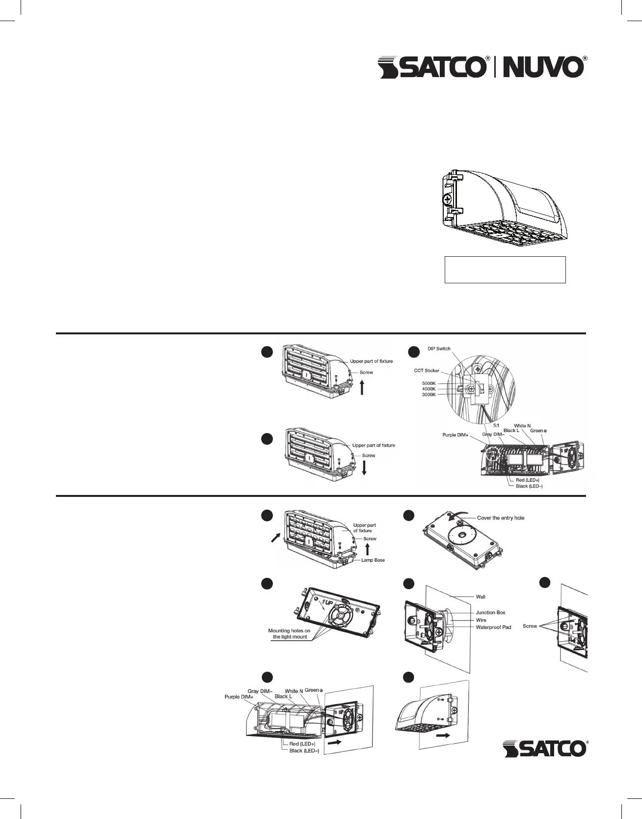
STEP 1: Use a screwdriver to unscrew the lamp
screws and remove the upper part of the xture.
STEP 2: Unscrew the cover of the entry hole on
the lamp base and remove the cover.
STEP 3: According to the embedded terminal
box, punch the corresponding mounting hole
on the light’s mount.
STEP 4: Put the input line in the embedded box
passes through the waterproof pad and then
passed through the lamp base.
STEP 5: Use screw to lock the lamp base on
the embedded junction box.
STEP 6: Connect the input wire and the
dimming wire of the light, then put the connected
wires into the embedded terminal box.
STEP 7: Use screws to lock the xture.
Installation is complete.
WARNING: Risk of Fire or Electric Shock
• To reduce the risk of re, electrical shock or injury to persons; read and follow all warnings
and installation instructions before installing.
• All installation should be performed by a qualied electrician.
• To avoid electric shock, ensure power is turned off before installation or inspection.
All wiring must be installed in accordance with Electrical Code and local electrical code.
• To prevent re, this xture is rated for use in 120-277V, 50-60Hz protected circuit and
105°C rated supply wire.
• To prevent product malfunction and/or electrical shock, this product must be properly
grounded.
• To avoid damage and/or product malfunction, do not modify the xture or replace
accessories without conrming with the supplier rst.
• To prevent wiring damage or abrasion, do not expose wiring to edges of sheet metal
or other sharp objects.
• Suitable for wet locations.
IMPORTANT: This product must be installed in accordance with the applicable installation code by a person familiar with the
construction and operation of the product and the hazards involved.
STEP 1: Remove screws with screw driver,
unscrew the upper part from xture.
STEP 2: Open xture, set up CCT through inside
DIP Switch, default switch gear is 4000K, dial
downward for positioning 3000K, dial upward for
5000K, dial to middle for 4000K. Users can dial
to positions for the CCT needed.
STEP 3: Close the xture after selecting CCT,
tighten the upper part to the back cover with
screws, CCT adjustment is done.
CCT SELECTABLE FULL CUTOFF
LED WALL PACK
Models: 65/671, 65/672, 65/673
Satco Products, Inc.
Brent wo od, NY 11717
CCT INSTRUCTIONS
INSTALLATION
INSTALLATION AND SAFETY INSTRUCTIONS
IMPORTANT: Read before installing xture. Retain for future reference.
© Copyright 2020 Satco Products, Inc. 5/20
4
2
Dimensions
320mmW x 181mmH x 174mmD
1
3
2
1
3
5
6 7


