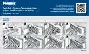
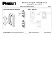
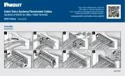
Panduit CT-1550 Manual


Læs gratis den danske manual til Panduit CT-1550 (2 sider) i kategorien Ikke kategoriseret. Denne vejledning er vurderet som hjælpsom af 27 personer og har en gennemsnitlig bedømmelse på 4.8 stjerner ud af 14 anmeldelser. Har du et spørgsmål om Panduit CT-1550, eller vil du spørge andre brugere om produktet?

Side 1/2
Part No. CT-1550
OPERATION INSTRUCTIONS
Contour Crimp
CONTROLLED CYCLE
CRIMPING TOOL
C
rimps most Panduit #22-#10 AWG
insulated terminals & splices; and
specific insulated disconnects.
for #22-#14 AWG terminations.
Provides UL Listed and CSA Certified terminations
with applicable Panduit terminals.
INSULATED TERMINAL CRIMPING
INSTRUCTIONS
NOTE: Visual inspection dots (formed by the
crimp dies) on the insulation sleeve verify
proper crimp cycle.
Two (2) dots for red and blue crimp
pocket
Three (3) dots for yellow crimp pocket.
1. With the handles in the closed position, (See
Figure 1), rotate the locator until the narrow slot
is centered between the crimp pockets (See
Figure 2). The locator will detent and “lockin
this position. Squeeze the handles to open the
tool. With the back of the terminal tongue
turned toward the color dots, insert the terminal
in the proper crimp pocket (See Figure 1) so
that the tongue slides into the locator slot (See
Figure 3). Refer to product packaging for
selection of proper crimp pocket.
2. Hold the terminal against the locator and close
the handles until the barrel is held snugly in
place—do not deform the barrel.
3. Insert the stripped wire into the terminal until
the wire stops in the recessed slot in the
locator. Refer to product packaging for wire
strip length.
4. Crimp the terminal by closing the handles until
the controlled cycle mechanism releases.
Upon release, the handles will open automati-
cally and the crimped terminal can be removed.
INSULATED SPLICE AND FULLY
INSULATED DISCONNECT CRIMPING
INSTRUCTIONS
1. With the handles in the open position, swing the locator out of the way (See Figure 4). The locator will detent and “lock”
in this position. For splices, insert the splice in the proper crimp pocket (See FIgure 1) so that the crimp is located on
the barrel of the splice (See Figure 5). For fully insulated disconnects, insert the disconnect in the proper crimp pocket
(See Figure 1) so that the crimp is located on the barrel of the disconnect (See Figure 6). Refer to product packaging
for selection of proper crimp pocket.
2. Close the handles until the barrel is held snugly in position—do not deform the barrel.
3. Insert the stripped wire into the barrel until the wire stops. Refer to product packaging for wire strip length. Crimp by
closing the handles until the controlled cycle mechanism releases. Upon release, the handles will open automatically
and the crimped splice or disconnect can be removed. After crimping, inspect that the crimp is centered on the
disconnect barrel in order to achieve optimal pullout performance.
4. For splices, remove the splice and repeat operation for crimping the other end of the splice.
Figure 4
Figure 5
Figure 6
Figure 7
©
Panduit Corp. 2017
P
A22151A04
Rev.: 06 1-2017
CT-1550
22 - 14
12 - 10
22 - 14
12 - 10
D
ie Closure Alignment
(not a crimp pocket)
L
ocator
Made in Germany
CRIMP POCKETS FOR
Pan-Term INSULATED
t
erminals, disconnects,
splices and wire joints.
Refer to product packaging
for wire range and proper
crimp pocket. Crimp pockets
are color coded to match
color of terminal insulator,
and identified with applicable
wire range.
Controlled cycle mechanism
prevents tool from opening
before crimp cycle is completed.
Manual release lever, push
forward in the event that
controlled cycle mechanism
must be released.
Cushioned Handle Grips
Figure 1
Figure 2
Figure 3
Email:
techsupport@panduit.com
EU Website: www.panduit.com/emea
EU Email: emeatoolservicecenter@panduit.com
Technical Support:
Tel: 1-800-777-3300
Panduit Europe EMEA Service Center
Tel: 31 (0) 546 580 452 Fax: 31 (0) 546 580 441
CT-1550
O
PERATION INSTRUCTIONS
Page: 1 of 2
CAUTION: Verify power is OFF
before working on wiring with this
tool. The cushioned grips are for
the user s comfort, and are not
intended to insulate against shock
while working on live electrical
circuits.
www.panduit.com
IN-SERVICE TOOLS - AFTER TOOLS HAVE BEEN IN SERVICE:
NEW TOOLS - BEFORE PLACING INTO SERVICE:
INSPECTION /MAINTENANCE
1. Twist the ends of the stripped wire together,
trim and set aside. Refer to product
packaging for wire strip length.
2
. With the handles in the position, swingopen
t
he locator out of the way (See Figure 4). The
l
ocator will detent and “lock” in this position.
I
nsert the wire joint from the back (locator)
s
ide of the crimp tool in the proper crimp
p
ocket (See Figure 1) so that the ribs of the
m
olded insulator (where applicable) are
p
ositioned against the crimp die (See Figure
9
). Refer to product packaging for selection of
p
roper crimp pocket.
3
. Close the handles until the barrel is held
s
nugly in position—do not deform the barrel.
4
. Insert the prepared wires into the wire joint.
C
rimp the wire joint by closing the handles
u
ntil the controlled cycle mechanism releases.
U
pon release, the handles will open
a
utomatically and the crimped joint can be
r
emoved.
I
NSULATED WIRE JOINT CRIMPING
INSTRUCTIONS
VISUAL INSPECTION
1. Visually inspect the tool for missing or loose
pins, then close the tool and note the return
action of the handles.
2. Swing the locator out of the way (See Figure
4), and inspect the crimping dies for worn,
chipped or broken edges.
3. If parts are missing, defective or damaged,
contact Panduit Customer Service for
information on repair or replacement of tools.
TROUBLESHOOTING
DIE CLOSURE INSPECTION
PRELOAD FORCE INSPECTION
Die closure is measured by using pin gages (dimensions listed in Table 1).
1. Clean the crimping dies and gage member surfaces.
2. Close the tool handles until the crimping dies are bottomed and the controlled cycle mechanism releas-
es. Keep the handles closed together.
3. Using the appropriate gage member, attempt to insert the NO GO gage into the die opening. The NO
GO side may partially enter the die closure but must NOT pass completely through. Perform this test
for both crimp pockets.
4. Repeat Step 3 with the appropriate GO gage for both crimp pockets. The GO side must enter and pass
completely through the die closures.
5. If both gage conditions are met, the tool is dimensionally correct. If either condition fails, contact Panduit
Customer Service, or Panduit EMEA Service Center for technical assistance.
1. Close the handles until the controlled cycle
mechanism is engaged but before the
mechanism releases.
2. Apply force to the handles 1-1/4" (32mm)
from the end of the handles, until the
controlled cycle release mechanism
releases. Record the reading using a force
gauge.
3. The force required to release the controlled
cycle release mechanism should be a
minimum of 15 pounds-force (67 N). If the
force required is less than 15 pounds-force
(67 N), contact Panduit Customer Service, or
Panduit EMEA Service Center for technical
assistance.
Table 1
Figure 8
Figure 9
All Panduit crimping tools are calibrated and inspected before they are
shipped from the factory. All new tools should be inspected before being
used.
New tools are shipped, factory lubricated, in protective packaging. After
inspection, simply clean any excess oil from the crimping dies and place into
service.
When the tool is not in use, keep the handles closed to prevent objects from
becoming lodged in the crimping area. Store the tool in a clean, dry area.
It is recommended that each operator of the tool be made aware of - and
responsible for following these maintenance steps.:
In-service tools should be cleaned and inspected at least ONCE A MONTH.
To clean-wipe with a clean cloth.
In-service tools should be lubricated ONCE A WEEK, and after every clean-
ing. Lubricate all pins, pivots and bearing surfaces with DOW CORNING
®
Molykote BR2 Plus. Do not use oil excessively.
Be sure to clean any excess oil from the crimping dies before using.
® Molykote BR2 Plus is the Registered Trademark of DOW CORNING
DIE CLOSURE GO / NO GO GAGE MEMBERS - TOOL NO. CT-1550
CRIMP POCKET “G” Dia. (GO) “NG” Dia. (NO GO)
22 - 14 0.101 0.109
12 - 10 0.147 0.155
1. With the handles in the closed position, (See Figure
1), rotate the locator until the wide slot is centered
between the crimp pockets (See Figure 7). The
locator will detent and “lock in this position.
Squeeze the handles to open the tool. With the back
of the disconnect tongue turned toward the color
dots, insert the disconnect in the proper crimp
pocket (See FIgure 1) so that the tongue slides into
the locator slot (See Figure 8). Refer to product
packaging for selection of proper crimp pocket.
2. Hold the disconnect against the locator and close the
handles until the barrel is held snugly in place—do
not deform the barrel.
3. Insert the stripped wire into the disconnect. Refer to
product packaging for wire strip length. Crimp the
disconnect by closing the handles until the controlled
cycle mechanism releases. Upon release, the
handles will open automatically and the crimped
disconnect can be removed.
I
NSULATED DISCONNECT CRIMPING
I
NSTRUCTIONS
Page: 2 of 2
©
Panduit Corp. 2017
OPERATION INSTRUCTIONS CT-1550


Produkt Specifikationer

Mærke: Panduit
Kategori: Ikke kategoriseret
Model: CT-1550

Har du brug for hjælp?

Hvis du har brug for hjælp til Panduit CT-1550 stil et spørgsmål nedenfor, og andre brugere vil svare dig


Ikke kategoriseret Panduit Manualer

Panduit

Panduit MIW094 Manual

2 September 2025
Panduit

Panduit MIW125 Manual

2 September 2025
Panduit

Panduit PES400 Manual

2 September 2025
Panduit

Panduit CUCGF06DPW1 Manual

2 September 2025
Panduit

Panduit CUEFRCKITW1 Manual

2 September 2025
Panduit

Panduit MIM125 Manual

2 September 2025
Panduit

Panduit CUSREORCPB1 Manual

2 September 2025

Ikke kategoriseret Manualer

Nyeste Ikke kategoriseret Manualer

Turbo Air

Turbo Air TBC-65SB-N6 Manual

2 September 2025
XPower

XPower BR-282A Manual

2 September 2025
Grunkel

Grunkel SAN-GRILLNG Manual

2 September 2025
AVer

AVer DL10 Manual

2 September 2025
Rigol

Rigol HDO1204 Manual

2 September 2025
XPower

XPower A-2B Manual

2 September 2025
Horizon

Horizon Micro FCJJ-44 Manual

2 September 2025