Rane DA 26 Manual

Rane Blander DA 26

Læs gratis den danske manual til Rane DA 26 (4 sider) i kategorien Blander. Denne vejledning er vurderet som hjælpsom af 2 personer og har en gennemsnitlig bedømmelse på 5.0 stjerner ud af 1.5 anmeldelser. Har du et spørgsmål om Rane DA 26, eller vil du spørge andre brugere om produktet?

Side 1/4
Manual-1
DA 26
DISTRIBUTION AMPLIFIER
OPERATORS MANUAL
WEAR PARTS: This product contains no wear parts.
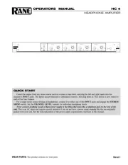
QUICK START
Are you in a hurry? For optimum system performance, we recommend reading the detailed Operating Instructions
below and on page Manual-4. For those who can’t wait, at least be aware of these points:
There are two inputs: Priority and Line.
The Priority Input sums with an Output when assigned by the Priority Assign Port, and Priority Detect is active.
The level of the Priority Input is unaffected by the AGC, Output Level controls or Remote Level controls.
The AGC includes a Target Level and Ratio.
The AGC only operates when the signal is within 26 dB of the Target Level. If the Line Input level is out of AGC range,
the 0 dB indicator on the AGC Gain Meter is off.
With the Ratio set to infinity:1, the AGC Gain Meter should indicate about 0 dB for nominal Line Input levels.
The AGC Fast/Slow switch only affects the gain reduction time constant. The gain increase time constant is fixed.
Only the Line Input is processed by the AGC, Crossover, Output Level controls and Remote level controls.
The three Crossover Outputs (full-range, high-pass and low-pass) may be selected by any of the six Outputs.
Set the initial Output levels using the Output Level controls located on the front panel.
Remote Level controls allow end user adjustment of Output level.
Any combination of Remote Ports may be controlled by a single Remote device.
Remote Level control provides automatic loudness compensation for low-pass Outputs. Loudness compensation is not
provided for full range Outputs.
The optional VR 1 Remote Level control provides audio taper control over a range of 0 dB to –80 dB.
Never connect anything except an approved Rane power supply to the Input that looks like a telephone jack on the rear of
the DA 26. This is an AC Input and requires specific voltage and current. This is not a good place to experiment or
improvise. Use only the supply sent with your DA 26.
SETUP AND OPERATION
The outline below is detailed in the procedure that follows.
1. Set Line Input level
2. Set AGC (Automatic Gain Control) Target Level and Ratio
3. Set Crossover frequency
4. Select Source for each Output (Full-range, High-pass or
Low-pass)
5. Set Output Level controls
6. Connect Output Remote Level controls
7. Setup the Priority Input for the intended source
8. Set the Priority Input automatic Detect threshold
9. Set Ducking depth for the application
10. Priority Assign selection
1. Connect a balanced line level source to the Line Input. The
Line Input accepts an unbalanced Input connected to (+)
and (GND). We do not recommend unbalanced operation
unless the distance to the source is less than 3 feet [one
meter].
2. The Line Input signal is processed by the AGC circuit. The
AGC GAIN meter 0 dB indicator lights when the Line
Input signal is within 26 dB of the set TARGET LEVEL.
For Line Input levels more than 26 dB below the Target
Level, the 0 dB indicator is off and AGC returns to unity.
The AGC GAIN indicates the amount of attenuation used
to make the Line Input level equal the set TARGET
LEVEL. For best results, the AGC GAIN meter should
indicate about 0 dB for nominal Line Input signals. The
best resolution for this adjustment is achieved with the
AGC RATIO set to :1.
The TARGET LEVEL is set in one of two ways:
a) If you have a source output level control, set the TAR-
GET LEVEL to the desired setting and adjust the Line
Input level so that the AGC GAIN meter indicates 0 dB
for nominal signal levels.
b) If a source output level control is not available, adjust
the TARGET LEVEL so that the AGC GAIN meter
indicates 0 dB for nominal Line Input levels. The
difference between the resulting AGC Target Level and
the desired Target Level is compensated with the
OUTPUT trims. With Input level and TARGET LEVEL
correctly set, adjust the AGC RATIO to the desired
value. We recommended values between 2:1 and :1 as
marked by the gray band. The soft-knee-response of the
AGC results in a natural sounding response with AGC
Ratios as high as :1.
continued on page Manual-4...
Manual-2
FRONT PANEL DESCRIPTION
PRIORITY GAIN trim and OL indicator: adjusts the gain for the PRIORITY INPUT. Set this trim to prevent overload-
ing the Input if the Priority Gain OL illuminates, turn down the GAIN.
PRIORITY DETECT trim and ACTIVE indicator: sets the threshold in dBu for the PRIORITY INPUT to override the
LINE INPUT. When the threshold has been reached, the ACTIVE indicator illuminates. Set the GAIN(), then set the
DETECT trim. The range of operation is +4 dBu to ON. The release time for the auto-detect circuit is fixed at about 6
seconds, after which the LINE INPUT signal returns to it's previous level.
PRIORITY DUCKER trim: sets the amount of attenuation applied to the LINE INPUT signal when the PRIORITY
INPUT is activated by the DETECT threshold. DUCKER depth is continuously adjustable over a range of 0 dB to –80 dB.
For equal mixing of PRIORITY and LINE, set the DUCKER to 0 dB. For PRIORITY replaces LINE operation, use –80 dB.
A value of –12 dB (1 o’clock) is typical for PRIORITY (page) talks over LINE (music) operation.
AGC TARGET LEVEL trim: is best set so the average signal at the LINE INPUT reads 0 dB on the GAIN meter. This
gives the best performance of the AGC (Automatic Gain Control). Active constant gain range of the AGC is ±12 dB (24 dB
range). When the Input falls 26 dB below the AGC Target Level, gain returns to unity. See Setup and Operation, step 2.
AGC RATIO trim: determines the Ratio applied to the AGC with a soft-knee response. Increased clockwise rotation
increases the amount of AGC. The full counter-clockwise position disables the AGC. The normal range of operation is
between 2:1 and :1 as marked by the gray band.
AGC SLOW/FAST release switch: determines the gain reduction time constant of the AGC circuit. SLOW = 230 ms (best
for music), FAST = 11 ms (best for voice). The gain increase time constant is fixed at 1100 ms.
AGC GAIN meter: indicates the amount of AGC applied to the LINE INPUT. The 0 dB GAIN indicator is off if the Input
is more than 26 dB below the Target Level.
CROSSOVER FREQUENCY switch and indicators: select the FREQUENCY for the 2-way Crossover when High-Pass
and/or Low-Pass outputs are used (80, 110,150 or 200 Hz). High, Low or Full-Range is selectable for each of the six
Outputs.
OUTPUT trims and Crossover select switches: The ±12 dB trims set the levels for each of the six Outputs. High, Low or
Full-Range is switch selectable for each of the six Outputs. Note: the Output trims do not affect Low-pass loudness
compensation or Priority Input level. See Setup and Operation, step 5.
POWER indicator LED: This yellow illumination device lights up to let the operator know the thing is plugged in.


Produkt Specifikationer

Mærke: Rane
Kategori: Blander
Model: DA 26

Har du brug for hjælp?

Hvis du har brug for hjælp til Rane DA 26 stil et spørgsmål nedenfor, og andre brugere vil svare dig


Blander Rane Manualer

Rane

Rane DA 216 Manual

20 Juni 2025
Rane

Rane RA 27 Manual

20 Juni 2025
Rane

Rane GE 30 Manual

20 Juni 2025
Rane

Rane CP R1 Manual

20 Juni 2025
Rane

Rane DA 26 Manual

20 Juni 2025
Rane

Rane MPE 47 Manual

20 Juni 2025
Rane

Rane FSC 22 Manual

20 Juni 2025
Rane

Rane ME 15 Manual

20 Juni 2025
Rane

Rane FDA 18 Manual

20 Juni 2025

Blander Manualer

Nyeste Blander Manualer

DNA

DNA HLC 10 MK2 Manual

17 Juni 2025
Roland

Roland VR-3 Manual

16 Juni 2025
DNA

DNA EF-MIX 4 Manual

16 Juni 2025
DNA

DNA MIX 4 EQ Manual

16 Juni 2025
DNA

DNA QFX6 Manual

15 Juni 2025
Globe

Globe SP30 Manual

13 Juni 2025
Globe

Globe SP20 Manual

13 Juni 2025
DNA

DNA CM8-DSP Manual

9 Juni 2025
DNA

DNA HLC 14 MK2 Manual

9 Juni 2025