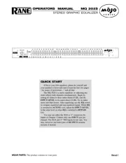
Rane CP 64 Manual

Rane Blander CP 64

Læs gratis den danske manual til Rane CP 64 (12 sider) i kategorien Blander. Denne vejledning er vurderet som hjælpsom af 3 personer og har en gennemsnitlig bedømmelse på 4.1 stjerner ud af 2 anmeldelser. Har du et spørgsmål om Rane CP 64, eller vil du spørge andre brugere om produktet?

Side 1/12
Manual-1
OPERATORS MANUAL CP 64
COMMERCIAL PROCESSOR
QUICK START
If you were the type that cheated on school book reports by just skimming through the reading assignments, then this
section is for you! It gives you not quite enough information to really know what you’re doing. But, if you follow the
recommended set up procedure, you should get at least a “B.”
Keep the amplifiers and the CP 64 turned off until all connections are made.
INTERNAL SETTINGS: Access to the following internal controls requires removal of the top cover. All internal
ever, you may need to change one or more for your system. See the INTERNAL ADJUSTMENTS description on page
Manual-8 for more details
Each Page Input has a 15 volt Phantom Power switch. The default is off.
The Page Priority switch assigns priority override to Page 1, Page 2 or NO (none). The default is Page 1. If a Page has
priority, it overrides the non-priority Page in the Zone(s) it is assigned. The NO priority setting allows the Pagers to mix.
Each Page Input may sum with the Program Pre- or Post-VCA. When set to Pre-VCA, Zone Level, EQ and Limiter
circuits act upon the Page. When summed Post-VCA, the Page is not influenced by Zone Level, EQ or Limiter circuits.
The default is Pre-VCA.
The Zone 1 Stereo/Mono switch default is Stereo.
There are two internal trim controls for the Program Priority detector. The Program Priority Threshold trim has a range
of - to -35 dBu with a default of -50 dBu. The Program Priority Release Time has a range of 2 to 20 seconds. The
default is 12 seconds.
PAGE INPUTS: Connect Page Inputs to the Euroblock on the rear panel and select the appropriate MIC or LINE
switch position for each. First, set the gain with the Page TRIM control, then set the Page DETECT THRESHOLD and
finally the Page Zone LEVEL.
PR 2 REMOTE: If you use the optional PR 2 remote (sold separately), wire it to the rear RMT ZONE ASSIGN
Euroblock as indicated. If you require remote control but do not wish to use a PR 2, any simple switch closure to GND will
work. These inputs are also TTL compatible (0 to 5 VDC). See wiring details on pages Manual 9-10.
PROGRAM INPUTS: Connect Program sources to the RCA PROGRAM INPUTS (L1, L2, L3 & P.) If you have a
priority program, like a jukebox, connect it to the PRIORITY Input. The Program PRIORITY ASSIGN switch assigns
priority override to Off, Zone 1, Zone 2, or Both. In the Zone(s) that it is assigned, the priority program is automatically
selected when signal is detected.
EXPAND OUTPUTS: Wire the EXPAND OUTPUT Euroblock for each Zone as required. These are cross-coupled
line drivers and may be used balanced or unbalanced. Each Expand Output can be Page-only, Program-only or Zone
signal. The Zone source will not include the Page if the Page is summed Post-VCA. Page is always available from the Page
source.
ZONE OUTPUTS: Wire the two ZONE OUT Euroblocks as required. These are cross-coupled line drivers and may
be used balanced or unbalanced. Set the LIMIT threshold as required.
ZR 1 REMOTE: You may use one or two ZR 1 Remotes with each CP 64. If you use the optional ZR 1 remote (sold
separately), wire it to the rear REMOTES Euroblock as indicated. If a ZR 1 remote is not used, any simple switch closure
to GND will work for the D0 and D1 pins. These pins are TTL compatible (0 to 5 VDC). The logic is inverse Gray Code.
Any ground referenced 5 volt DC control may be used as the input to V
1
or V
2
. Do not ground the Vr
1
or Vr
2
pins. See
wiring details on pages Manual 9-10.
The CP 64 is very versatile. While this makes a large number of system applications possible, it also results in complex-
ity. For this reason, it is important to use an organized approach for setup and calibration. A highly recommended setup
procedure appears on page Manual-11. By following it you will encounter fewer problems and reduce the need to increase
our collective phone bills.
WEAR PARTS: This product contains no wear parts.
Manual-2
CP 64 FRONT PANEL
PAGING ZONE ASSIGN switches select the zone(s) a Page signal is sent to. The RMT position activates the rear panel
RMT ZONE ASSIGN port, allowing the optional PR 2 wired remote to assign the active page Zone(s).
ACTIVE indicators light when a Page input signal reaches the Page Detect Threshold. Note that a Page is always Active
when its Page Detect Threshold is set to minimum.
ZONE 1 AND ZONE 2 PAGING LEVEL controls adjust the Paging Level in each Zone.
PROGRAM INPUT LEVEL “stereo”controls allow independent adjustment of level for each Program Input.
DUCKER OFF/ON switches turn the Ducker ON or OFF for each Zone.
DUCKER DEPTH controls allow setting Ducker Depth (the amount of Program attenuation during a Page) from 50 dB
(ccw) to 6 dB (cw) for each Zone.
ZONE PROGRAM SELECT switches assign one of four Program Inputs in each Zone.
ZONE RMT switches, when pushed in, enable the Remotes port for a Zone. This turns control of Zone Level and Zone
Program Select over to the Remotes port. Front panel Zone LEVEL and Zone PROGRAM SELECT controls are inactive
when RMT is selected. Two optional wired ZR 1 remotes may be connected to the Remotes port. An object smaller in
diameter than the switch button is required to engage the RMT switches.
ZONE SIG/OL indicators show SIGnal present at +20 dBu and OverLoad at 16 dBu (4 dB before clipping) respectively.
Signal indicators are located pre-EQ and pre-VCA.
ZONE LEVEL controls adjust the overall Level for a given Zone.
GRAPHIC EQ controls are provided for each Zone. Zone 1 controls are “stereo,” with each slider controlling the response
of both Left and Right channels. These controls allow ±12 dB adjustment of seven ISO center frequencies on two octave
centers.
PWR indicator lights when the CP 64 is connected to a powered RS 1 power supply.


Produkt Specifikationer

Mærke: Rane
Kategori: Blander
Model: CP 64

Har du brug for hjælp?

Hvis du har brug for hjælp til Rane CP 64 stil et spørgsmål nedenfor, og andre brugere vil svare dig


Blander Rane Manualer

Rane

Rane AP 13 Manual

24 Juni 2025
Rane

Rane CP 64 Manual

22 Juni 2025
Rane

Rane MP 2S Manual

22 Juni 2025
Rane

Rane MA 3 Manual

21 Juni 2025
Rane

Rane NM 48 Manual

21 Juni 2025
Rane

Rane MP 22x Manual

21 Juni 2025
Rane

Rane MA 6s Manual

21 Juni 2025
Rane

Rane HC 4 Manual

21 Juni 2025
Rane

Rane MM 12 Manual

21 Juni 2025
Rane

Rane MQ 302S Manual

21 Juni 2025

Blander Manualer

Nyeste Blander Manualer

Glemm

Glemm MMX 54ZM Manual

21 Juni 2025
Roland

Roland M-5000 Manual

20 Juni 2025
DNA

DNA HLC 10 MK2 Manual

17 Juni 2025
Roland

Roland VR-3 Manual

16 Juni 2025
DNA

DNA EF-MIX 4 Manual

16 Juni 2025
DNA

DNA MIX 4 EQ Manual

16 Juni 2025
DNA

DNA QFX6 Manual

15 Juni 2025
Globe

Globe SP30 Manual

13 Juni 2025
Globe

Globe SP20 Manual

13 Juni 2025