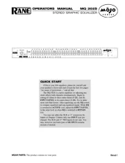
Rane GE 215 Manual

Rane Blander GE 215

Læs gratis den danske manual til Rane GE 215 (4 sider) i kategorien Blander. Denne vejledning er vurderet som hjælpsom af 2 personer og har en gennemsnitlig bedømmelse på 4.6 stjerner ud af 1.5 anmeldelser. Har du et spørgsmål om Rane GE 215, eller vil du spørge andre brugere om produktet?

Side 1/4
Manual-1
OPERATORS MANUAL GE 215
GRAPHIC EQUALIZER
QUICK START
So tell me honestly, do you actually read the manuals or do you just want to connect the thing and go? If you are one of
the “gotta go now” crowd please read this short section. Even if you read slowly so as to savor every syllable it only takes a
couple of minutes and may save more of your valuable time later. The rest of this manual is dedicated to those who really
want to know all the nitty-gritty details.
Wait a minute before plugging in the power supply. Hopefully the equipment to and from the GE 215 is balanced, with
pin 2 “hot.” From the line level outputs preceding the GE 215, connect a pair of XLR male connectors to the rear panel
connectors to the rear panel OUTPUT jacks, to the next line level device in the signal chain.
Now plug in the power supply. The yellow POWER LED should illuminate, and if you have an audio source working
and the rest of the signal chain completed, you will hear audio. With sliders centered and the LEVEL controls at 7
(corresponds to about 2 o’clock), depress the BYPASS switches. If any difference in level exists, adjust each channel’s
LEVEL control so the same volume exists whether it’s BYPASS is in or out. You now have an expensive jumper wire.
Fully utilizing the capabilities of the GE 215 requires moving some of the sliders, but you already knew that. To make best
use of the GE 215, use some sort of an analyzer to help adjust the sliders properly.
Never connect anything except an RS 1 or other approved Rane AC power supply to the thing that looks like a
telephone jack on the rear of the unit. This is an AC supply and requires some special attention if you do not have an
operational power supply exactly like the one that was originally packed with your unit.
GE 215 CONNECTION
When first connecting the GE 215 to other components,
connect the power supply last. This gives you a chance to
make mistakes and correct them without damaging your
fragile speakers, ears and nerves.
INPUTS
Both XLR and Euroblock Inputs are wired in parallel and
are actively balanced. Each works equally well. Choose
strictly from a required hardware point-of-view, there are no
performance trade-offs. The wiring convention adheres to
American, British and International standards of pin 2 being
hot (+), pin 3 being return (–), and pin 1 being shield.
Unbalanced operation involves using only pin 2 or “+” as
signal, and pin 1 as shield or ground. It is not necessary to
short any inputs to ground—it doesn’t hurt, it’s just not
necessary. Use pin 1, or the shell, for shield ground.
OUTPUTS
The Outputs mimic the Inputs. Balanced output requires
using pin 2 and pin 3 for the signal. It does not require pin 1
or shield. The signal exists differentially between the two
balanced leads; ground is not involved. For hum-free systems
ground is used only for shielding.
SIGNAL LEVELS
Signal levels from -10 dBV to +4 dBu are considered
normal and within range (at least 20 dB of headroom exists
above these levels). Do not directly connect microphones into
the GE 215. These require a mic preamp.
WEAR PARTS: This product contains no wear parts.
Manual-2
FRONT PANEL DESCRIPTION
POWER LED illuminates whenever the appropriate power supply is connected to the unit with the correct line voltage
source.
Channel BYPASS switches and LEDs: When the BYPASS switch is in the in position the red BYPASS LED illuminates
and the channel is in the BYPASS mode. In this mode the audio signal is routed directly from the INPUT to the OUTPUT
jacks without passing through any active circuitry (often referred to as hard-wire bypass). Use this switch to compare
equalized and unequalized material. In the event of power failure, the GE 215 automatically goes into BYPASS.
Channel OVERLOAD indicators illuminate if any section of the same Channel of the GE 215 is within 3 dB of clipping.
Occasional blinking of this LED is acceptable, but if it remains on more than intermittently, turn down either the Channel’s
LEVEL control or reduce the output level of the preceding component to avoid distortion.
Channel LEVEL controls set the Level of the signal coming into the GE 215. Turn this control down if the OVERLOAD
LED lights up in it’a Channel steadily (meaning too strong an Input signal). Since actual unity gain depends on varying
slider settings (which is why we have not marked a unity gain position on the front panel), use the BYPASS switch to
determine the exact unity gain position of this LEVEL control by comparing EQ and BYPASS loudness.
Filter Level slide controls set output levels of each of the 30 bandpass filters for each Channel.


Produkt Specifikationer

Mærke: Rane
Kategori: Blander
Model: GE 215

Har du brug for hjælp?

Hvis du har brug for hjælp til Rane GE 215 stil et spørgsmål nedenfor, og andre brugere vil svare dig


Blander Rane Manualer

Rane

Rane DA 216 Manual

20 Juni 2025
Rane

Rane RA 27 Manual

20 Juni 2025
Rane

Rane GE 30 Manual

20 Juni 2025
Rane

Rane CP R1 Manual

20 Juni 2025
Rane

Rane DA 26 Manual

20 Juni 2025
Rane

Rane MPE 47 Manual

20 Juni 2025
Rane

Rane FSC 22 Manual

20 Juni 2025
Rane

Rane ME 15 Manual

20 Juni 2025
Rane

Rane FDA 18 Manual

20 Juni 2025

Blander Manualer

Nyeste Blander Manualer

DNA

DNA HLC 10 MK2 Manual

17 Juni 2025
Roland

Roland VR-3 Manual

16 Juni 2025
DNA

DNA EF-MIX 4 Manual

16 Juni 2025
DNA

DNA MIX 4 EQ Manual

16 Juni 2025
DNA

DNA QFX6 Manual

15 Juni 2025
Globe

Globe SP30 Manual

13 Juni 2025
Globe

Globe SP20 Manual

13 Juni 2025
DNA

DNA CM8-DSP Manual

9 Juni 2025
DNA

DNA HLC 14 MK2 Manual

9 Juni 2025