Rane PE 17 Manual
Læs gratis den danske manual til Rane PE 17 (4 sider) i kategorien Blander. Denne vejledning er vurderet som hjælpsom af 7 personer og har en gennemsnitlig bedømmelse på 4.4 stjerner ud af 4 anmeldelser. Har du et spørgsmål om Rane PE 17, eller vil du spørge andre brugere om produktet?
Side 1/4

Manual-1
PE 17
PARAMETRIC EQUALIZER
OPERATORS MANUAL
QUICK START
Those who choose not to read this modest informational snippet (intended to ward off one of life’s embarrassing
moments) are those who wish to hasten the point at which their entire sound system locks up, screams unmercifully,
shatters windows, causes dogs to howl, babies to cry, and melts all the compression drives, dripping molten titanium all
over the hand-polished walnut decor. Pity.
There are only a few things to check when using a PE 17. Always set both GAIN controls as close to the top of the
panel as possible without causing the OL LED to light constantly. Use the CUT FILTERS to tailor the bandwidth for each
application. Always double check that each FREQx multiplier switch (located beneath each FREQ control) is set to the
correct position. Great surprises result from false settings.
For extra-deep notching applications, use Bands 3 and 4 and set them exactly the same. Notches as deep as 30 dB are
possible, since Bands 3 and 4 are in series while most other bands are in parallel (see the Block Diagram in the Specifica-
tions Section).
Hook-up is simple. The PE 17 accepts all combinations of balanced or unbalanced, XLR or ¼" connectors. However,
the INPUT connectors are wired in parallel and may not be used together. Use only one at a time. They will not function as
a summing type of input for two different sources, but they may be used in a daisy chain fashion to feed other units. On the
other hand (to randomly pick a hackneyed expression), you may use the paralleled Outputs to drive two destinations.
Never connect anything except a Rane approved AC power supply to the thing that looks like a red telephone jack on
the rear of the PE 17.
WEAR PARTS: This product contains no wear parts.

Manual-2
FRONT PANEL DESCRIPTION
OVERLOAD indicator: This red LED illuminates whenever the signal level at any of five critical nodes comes within 3-4
dB of clipping.
Overall BYPASS switch & indicator: Engaging this pushbutton energizes the Bypass relay. This provides a complete
hard-wire Bypass of the PE 17 with no active electronics in the signal path. A red LED indicates the unit is in the BYPASS
mode. In the out (LED off) position, the Input is routed through the active electronics. The Bypass relay is wired such that
upon power failure it reverts to the BYPASS condition, thus providing a “fail-safe” feature.
IN & OUT GAIN controls: set the relative IN and OUT gain structures. The range of each is ±12 dB; however, note that
the labeling is to each other, e.g., the top of the IN control reads +12 dB while the top of the OUT control reads -12opposite
dB. Configured this way, whenever they are held and moved together the overall gain through the PE 17 stays at unity.
Positioning these controls (together) as far toward the top of the panel as possible (without lighting the OL indicator) yields
the best signal-to-noise performance.
LOW & HIGH CUT FILTER controls: set the corner frequencies of the band limiting filters. The frequencies shown
represent the -3 dB points for each filter. When the sliders are located at their bottom-most positions, the filters are at their
lowest and highest extremes and thus, effectively bypassed.
FILTER LEVEL control: The center detent position guarantees flat response through the respective filter due to its
grounded center-tap design. Full clockwise rotation yields 12 dB of boost, while full counterclockwise rotation gives you
15 dB of cut.
FREQUENCY MULTIPLIER switch: The markings on this three position slide switch indicate the factor by which the
calibrations of the Frequency Sweep control (7) are multiplied. For instance, if the range switch is in the “x0.1” position and
the FREQ knob is at “460,” then the actual center frequency of the filter is 46 Hz. Operation of this switch in conjunction
with the FREQ control yields a range of 10 Hz to 20 kHz for each band.
FREQUENCY sweep control: increases the center Frequency of the filter band as it is turned clockwise. It is calibrated
from “100” to “2k.” The exact Frequency is determined by multiplying the value indicated by the Frequency Range switch
(6) setting.
Individual band BYPASS switch & indicator: Each of the five filter BYPASS switches disables the respective filter,
providing instant comparison between flat response and equalized response. The red LED illuminates when the band is in
the BYPASS mode.
BANDWIDTH control (Q): Full counterclockwise rotation yields a Bandwidth of 1/30 octave (Q=43) in the respective
filter, while full clockwise rotation gives a 2.0 octave (Q=0.67) Bandwidth.
POWER indicator: When this yellow LED is lit, the unit is ready to command.
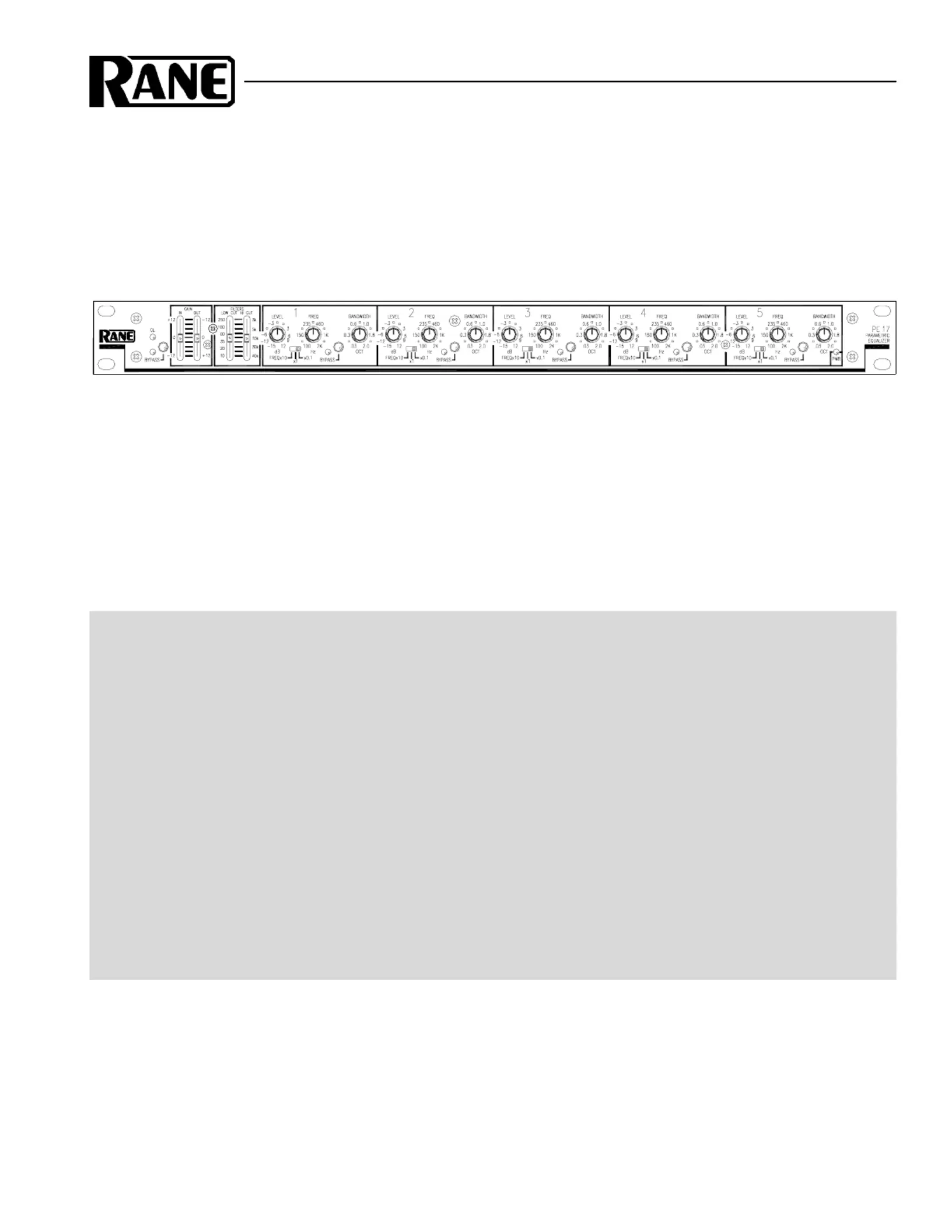
Produkt Specifikationer
Mærke: | Rane |
Kategori: | Blander |
Model: | PE 17 |
Har du brug for hjælp?
Hvis du har brug for hjælp til Rane PE 17 stil et spørgsmål nedenfor, og andre brugere vil svare dig
Blander Rane Manualer
24 Juni 2025
22 Juni 2025
22 Juni 2025
21 Juni 2025
21 Juni 2025
21 Juni 2025
21 Juni 2025
21 Juni 2025
21 Juni 2025
21 Juni 2025
Blander Manualer
- Unold
- KeMar
- Bosch
- Moulinex
- Audibax
- DBX
- AEG
- Analogue Solutions
- Steren
- Alto
- Zelmer
- Dynacord
- Mesko
- Gorenje
- Qtx
Nyeste Blander Manualer
13 August 2025
12 August 2025
12 August 2025
12 August 2025
12 August 2025
12 August 2025
12 August 2025
9 August 2025
9 August 2025
8 August 2025