Rane RPE 228 Manual

Rane Blander RPE 228

Læs gratis den danske manual til Rane RPE 228 (8 sider) i kategorien Blander. Denne vejledning er vurderet som hjælpsom af 4 personer og har en gennemsnitlig bedømmelse på 4.5 stjerner ud af 2.5 anmeldelser. Har du et spørgsmål om Rane RPE 228, eller vil du spørge andre brugere om produktet?

Side 1/8
Manual-1
OPERATORS MANUAL RPE 228
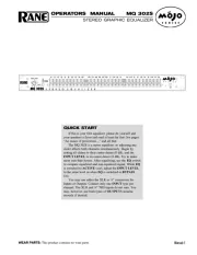
REMOTE PROGRAMMABLE EQUALIZER
QUICK START
Read this section if you want to install and operate the RPE 228 without wading through the detailed descriptions in this
manual. If the control software has not yet been installed on your computer, refer to SOFTWARE OPERATION on page
Manual-5 first.
Turn the amplifier(s) down or off until all connections are complete. Connect balanced audio INPUTS and OUTPUTS
to the handy Euroblock connectors on the rear. Connect the RW 232 INPUT jack on the rear to a serial (COM) port on a
connect between units in a rack). The cable or adaptor must not be a null-modem type.
Locate the RW 232 DEVICE ADDRESS switch on the rear panel. If this unit is to be tested by itself, set it to 1’ by
setting all switches off (down), except switch one (labeled ‘1’ on the chassis, the right-most switch). If there is more than
one unit, refer to SETTING THE DEVICE ADDRESS to set a unique number.
Apply power by connecting the RS 1 remote power supply to the red telephone-style jack on the rear of the unit.
CAUTION: don’t connect anything but an approved RANE power supply to this jack. If the RS 1 and the RPE 228 are
getting power, the front panel yellow POWER light will be on.
Start your computer, run Windows
®
, and launch our software by double-clicking on the RaneWare
®
icon. The System
Setup window may appear. If it doesn’t, select System Setup from the Setup menu. Be careful to select the COM port
which is physically connected to the RPE 228. Click OK. Now, the Device Selection window may appear. If it doesn’t,
choose Select from the Device menu. Click on Poll,and the Devices Found will display the number of units found.
Click the Stop button. Select the unit listed in the Device Selection window and click OK. If no unit was found, please
refer to the TROUBLESHOOTING section.
Several clues indicate communication between the computer and the RPE 228. The yellow COM (communications)
lights on the unit should flash periodically. The Memory numbers (1-16) near the top of the computer screen should be
black rather than grey. Clicking the BYPASS button on the screen causes one Channel of the unit to enter bypass.
WEAR PARTS: This product contains no wear parts.
Windows
is a registered trademark of Microsoft Corporation.
RaneWare is a registered trademark of Rane Corporation
Manual-2
FRONT PANEL DESCRIPTION
POWER indicates that the unit is happily connected to a powered remote supply.
Parameter Switch adjusts the frequency of the Low-Cut filters for each Channel incrementally up to the maximum setting,
then down to the minimum setting, and back.
COM (yellow, communications) flashes when a message for the unit or the specific Channel is received from a PC compat-
ible computer. There is a brief flash when using the Remote Switch Interface is used.
BYPASS (red) lights whenever the audio relay Bypass for the Channel is active. This occurs for a few seconds after power-
up, or when BYPASS is selected in RaneWare.
SIGNAL (green) indicates the presence of a significant audio signal on the Input to the Channel (typically -27 dBu).
CLIP (red) flashes when an audio level for the Channel in the unit approaches the clipping level (typically 3 dB below
clipping).
RPE 228 CONNECTION
When connecting the RPE 228 to other components in
your system for the first time, leave the power supply for last.
This will give you a chance to correct any mistakes before
any damage is done to your speakers, ears, etc.
The RPE 228 will operate at moderately high ambient
temperatures. Large racks of equipment may generate excess
heat, requiring extra space beween units, and/or forced air
ventilation to reduce the ambient temperature in the rack.
The RPE 228 has balanced Inputs and Outputs, with
chassis-grounded shields. This chassis ground is not signal
ground, although the two grounds are connected internally.
The chassis ground is intended to be connected to an earth
ground. The RPE 228 is intended to be connected to other
balanced equipment with chassis-grounded shields. Connect
the non-inverting audio lines to the ‘+’ terminals, and the
inverting lines to the ‘’ terminals. Connect the cable shields
to the center terminal on the terminal block. Connect shields
at both ends of the cables.
There is a #6-32 screw provided for chassis ground.
Connect a wire from this point to a known earth ground, such
as an amplifier chassis. This may not be necessary when
installed in a rack with other grounded units.
The RPE 228 requires a Rane RS 1 or compatible power
supply, provided with each unit. Optionally, our model RAP
10 power supply provides power for up to ten units at a time.
To control the units from a computer, use nine-pin RS-232
cables which are 50 feet or shorter. The cable must not be a
null-modem type. A short cable is supplied for connecting
adjacent units. Daisy-chain up to 16 units at a time by
connecting the COM port on the computer to the INPUT
connector on the first unit, and the OUTPUT connector of
each unit to the next unit’s INPUT.
The DEVICE ADDRESS switch identifies each unit with
an ‘address’, and must be set uniquely for each unit. The
switches form a binary code from 0 through 255. Only the
numbers 1-250 may be used. The place values of each switch
are marked on the rear panel. To set a specific address, refer
to the “Setting the Device Address” section.
The REMOTE SWITCH interface provides contact closure
control for up to eight preset memories. No computer is required
after the initial setup. There are nine screw terminals; one is
chassis ground, and the other eight are for Memories 1-8.
Connection of one of these to ground causes both Channels of
the unit to recall a preset Memory. Multiple units may be
controlled by connecting these terminals in parallel. Either
momentary or latching switches may be used. A latching switch
should only close one contact at a time. Use of a latching switch
results in an additional Memory recall upon power-up.


Produkt Specifikationer

Mærke: Rane
Kategori: Blander
Model: RPE 228

Har du brug for hjælp?

Hvis du har brug for hjælp til Rane RPE 228 stil et spørgsmål nedenfor, og andre brugere vil svare dig


Blander Rane Manualer

Rane

Rane DA 216 Manual

20 Juni 2025
Rane

Rane RA 27 Manual

20 Juni 2025
Rane

Rane GE 30 Manual

20 Juni 2025
Rane

Rane CP R1 Manual

20 Juni 2025
Rane

Rane DA 26 Manual

20 Juni 2025
Rane

Rane MPE 47 Manual

20 Juni 2025
Rane

Rane FSC 22 Manual

20 Juni 2025
Rane

Rane ME 15 Manual

20 Juni 2025
Rane

Rane FDA 18 Manual

20 Juni 2025

Blander Manualer

Nyeste Blander Manualer

DNA

DNA HLC 10 MK2 Manual

17 Juni 2025
Roland

Roland VR-3 Manual

16 Juni 2025
DNA

DNA EF-MIX 4 Manual

16 Juni 2025
DNA

DNA MIX 4 EQ Manual

16 Juni 2025
DNA

DNA QFX6 Manual

15 Juni 2025
Globe

Globe SP30 Manual

13 Juni 2025
Globe

Globe SP20 Manual

13 Juni 2025
DNA

DNA CM8-DSP Manual

9 Juni 2025
DNA

DNA HLC 14 MK2 Manual

9 Juni 2025