Salus PMV21 Manual
Salus
Ikke kategoriseret
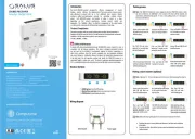
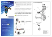
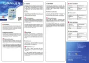
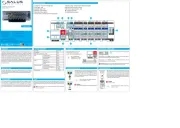
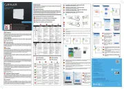
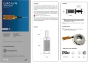
PMV21
| Mærke: | Salus |
| Kategori: | Ikke kategoriseret |
| Model: | PMV21 |
Har du brug for hjælp?
Hvis du har brug for hjælp til Salus PMV21 stil et spørgsmål nedenfor, og andre brugere vil svare dig
Ikke kategoriseret Salus Manualer

1 Oktober 2025
25 August 2025
13 August 2025
12 August 2025
12 August 2025
12 August 2025
30 Juli 2025
29 Juli 2025
29 Juli 2025
29 Juli 2025
Ikke kategoriseret Manualer
- Emis
- Riedel
- KS Tools
- Pioneer
- Chauvet
- Vertiv
- Narwal
- XFX
- Girmi
- Charge Amps
- GMB Gaming
- NUK
- L.R.Baggs
- Livoo
- GEEKOM
Nyeste Ikke kategoriseret Manualer

5 December 2025

5 December 2025

5 December 2025

5 December 2025

5 December 2025

5 December 2025

5 December 2025

5 December 2025

5 December 2025

5 December 2025