Satel S-3 Manual
Læs gratis den danske manual til Satel S-3 (2 sider) i kategorien Deur-/ramme sensor. Denne vejledning er vurderet som hjælpsom af 27 personer og har en gennemsnitlig bedømmelse på 4.7 stjerner ud af 14 anmeldelser.
Har du et spørgsmål om Satel S-3, eller vil du spørge andre brugere om produktet?
Produkt Specifikationer
| Mærke: | Satel |
| Kategori: | Deur-/ramme sensor |
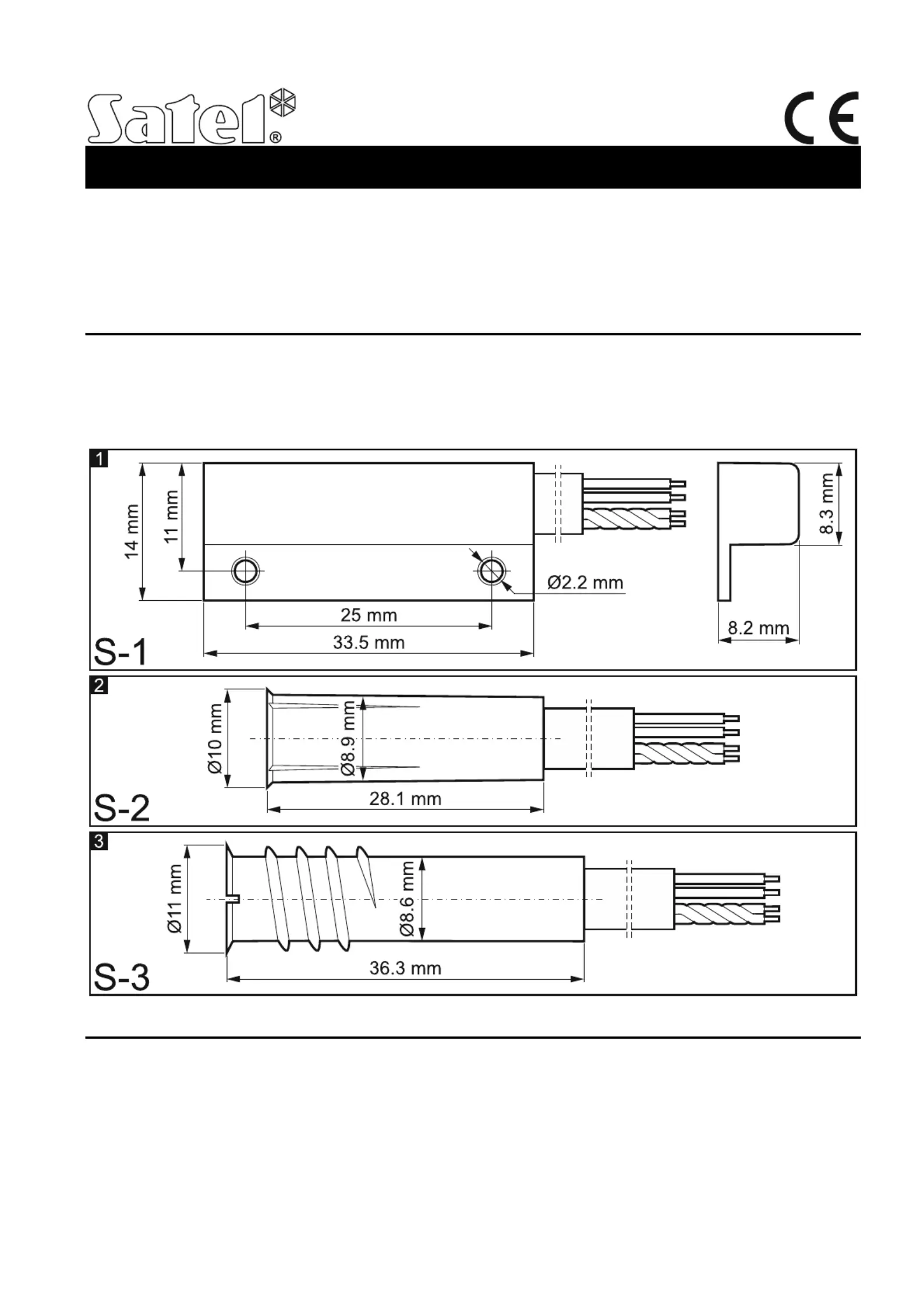
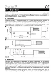
| Model: | S-3 |
| Vægt: | 43 g |
| Velegnet til: | Dør/vindue |
| Produktfarve: | Rustfrit stål |
| Certificering: | EN 50131-1, EN 50131-2-6 |
| Strømforsyning indgangsspænding: | 20 V |
Har du brug for hjælp?
Hvis du har brug for hjælp til Satel S-3 stil et spørgsmål nedenfor, og andre brugere vil svare dig
Deur-/ramme sensor Satel Manualer
Deur-/ramme sensor Manualer
- Avidsen
- Emos
- Fibaro
- Caliber
- ORNO
- Tellur
- Inovonics
- Kanlux
- Sonoff
- Abus
- Somfy
- KlikaanKlikuit
- Vivanco
- Hama
- Interlogix
Nyeste Deur-/ramme sensor Manualer