5/8/16-Port Gigabit Ethernet Switch
• TEG1005D/TEG1005M/TEG1008M/TEG1016M/TEG1116M
9-Port 10/100M Ethernet Desktop Switch
5-Port Fast Ethernet Switch
• Screw (thread diameter: 3 mm, length: 14 mm, head diameter: 5.2 mm) × 2
• Plastic anchor (height: 6.6 mm, inner diameter: 2.4 mm, length: 26.4mm) × 2
• Quick installation guide
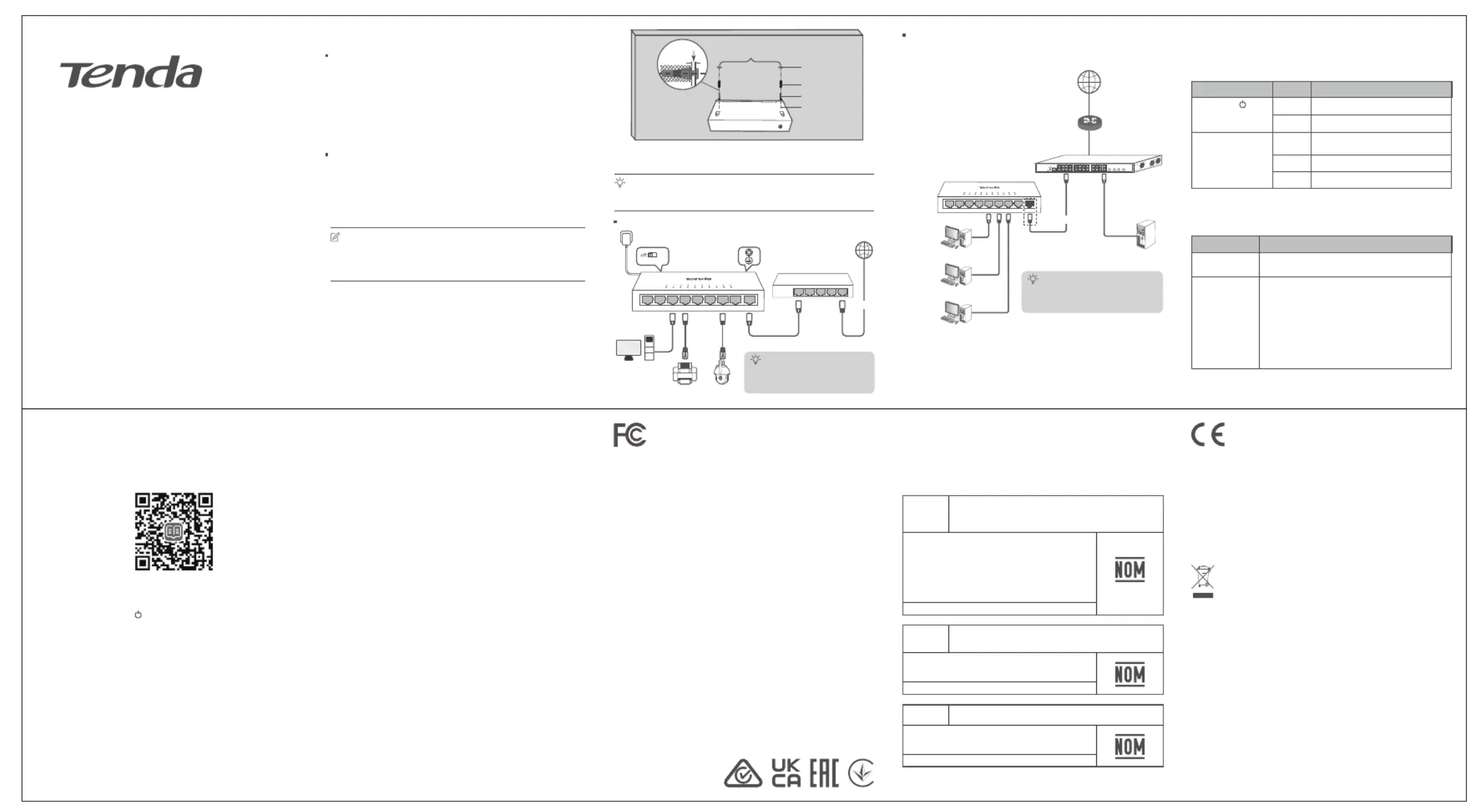
TEF1109D is used for illustrations here unless otherwise specified.
The actual product prevails.
Distance between the 2 holes
LAN L AN LA N LAN1 2 3 4 WAN
Switch (Example: TEF1109D)
• Quick installation guide
TEG1005D/TEF1005D/TEG1005M/TEG1008M/TEF1109D
All switches of this series support standard
mode. For TEG1016M, TEG1116M and
TEF1109D, this mode is VLAN off.
Only TEG1016M, TEG1116M and TEF1109D
support VLAN mode. Here, this mode is VLAN
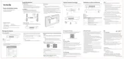
The switch is powered on.
The switch is powered off.
The port is connected, but no data is being
transmitted over the port.
Blinking Data is being transmitted over the port.
Off The port is not connected.
Default mode. In this mode, all ports can communicate with
In this mode, the downlink ports are isolated from each other,
but can communicate with the uplink ports. This mode helps
isolate DHCP broadcast and reduce broadcast storm.
− TEG1016M/TEG1116M: Ports 15-16
− TEG1016M/TEG1116M: Ports 1-14
(TEF1109D/TEG1016M/TEG1116M)
Q1: The power indicator ( , PWR or Power) does not light up. What
- Ensure that the power adapter is connected to the switch and the
- Ensure that the switch is powered on.
- Ensure that the input voltage matches the value required by the switch.
Q2: The Link/Act indicator (1-5/8/9/16) of the switch is off. What
- Ensure that the Ethernet cable is not damaged.
- Ensure that the Ethernet cable between the switch and the attached
device is connected properly, and the length of the Ethernet cable is
within standard length 100m.
- Ensure that the switch is powered on.
- Ensure the connected device is powered on and working properly.
Before operating, read the operation instructions and precautions to be taken,
and follow them to prevent accidents. The warning and danger items in other
documents do not cover all the safety precautions that must be followed.
They are only supplementary information, and the installation and maintenance
personnel need to understand the basic safety precautions to be taken.
− For wall mounting, the device is only suitable for mounting at heights ≤ 2 m.
− Operating environment: Temperature: 0°C- 40°C (32°F - 104°F);
Humidity: (10% - 90%) RH, non-condensing; Storage environment:
Temperature: -20°C - 70°C (-4°F - 158°F); Humidity: (5% - 90%) RH,
− The mains plug is used as the disconnect device and shall remain readily
− The power socket shall be installed near the device and easily accessible.
− Only use attachments/accessories specified by the manufacturer.
− Do not block any ventilation openings.
− Keep the device away from water, heat sources, high electric field, high
magnetic field, and inflammable and explosive items.
− Keep the operating environment clean. Remove dust from the device
regularly. Cut power before cleaning.
− Ensure proper grounding before device operation. Refer to the Lightning
Protection Guide on the official website for guidance.
− Disassembling or modifying the device or its accessories without
authorization voids the warranty, and might cause safety hazards.
− If such phenomena as smoke, abnormal sound or smell appear when you
use the device, immediately stop using it and disconnect its power supply,
unplug all connected cables, and contact the after-sales service personnel.
− Disconnect the power source during servicing.
− Refer all servicing to qualified service personnel.
− The device’s marking information can be found on its surface.
For the latest safety precautions, see Safety and Regulatory Information
This equipment has been tested and found to comply with the limits for a
Class A digital device, pursuant to Part 15 of the FCC Rules. These limits are
designed to provide reasonable protection against harmful interference
when the equipment is operated in a commercial environment. This
equipment generates, uses, and can radiate radio frequency energy and, if
not installed and used in accordance with the instruction manual, may
cause harmful interference to radio communications. Operation of this
equipment in a residential area is likely to cause harmful interference in
which case the user will be required to correct the interference at his own
Operation is subject to the following two conditions: (1) this device may not
cause harmful interference, and (2) this device must accept any
interference received, including interference that may cause undesired
Any changes or modifications not expressly approved by the party
responsible for compliance could void the user's authority to operate the
NOTE: (1) The manufacturer is not responsible for any radio or TV
interference caused by unauthorized modifications to this equipment. (2)
To avoid unnecessary radiation interference, it is recommended to use a
This is a Class A product.
Warning: Operation of this equipment in a residential environment could cause radio
interference. In which case the user may be required to take adequate measures.
NOTE: (1) The manufacturer is not responsible for any radio or TV interference
caused by unauthorized modifications to this equipment. (2) To avoid unnecessary
radiation interference, it is recommended to use a shielded RJ45 cable.
Declaration of Conformity
Hereby, SHENZHEN TENDA TECHNOLOGY CO., LTD. declares that the device
(Switch) is in compliance with directives 2014/35/EU and 2014/30/EU.
The full text of the EU Declaration of Conformity is available at the following internet
address: https://www.tendacn.com/download/list-9.html
This product bears the selective sorting symbol for Waste Electrical and Electronic
Equipment (WEEE). This means that this product must be handled pursuant to
European directive 2012/19/EU in order to be recycled or dismantled to minimize its
impact on the environment.
User has the choice to give his product to a competent recycling organization or to
the retailer when he buys a new electrical or electronic equipment.
LA OPERACIóN DE ESTE DISPOSITIVO ESTA SUJETA A LAS SIGUIENTES
a) Es posible que este equipo o dispositivo no cause interferencia perjudicial.
b) Este equipo o dispositivo debe aceptar cualquier tipo de interferencia, incluyendo
la que pueda causar su operación no deseada.
Estimado usuario: Antes de utilizar este producto lo invitamos a leer el siguiente
manual para que conozca todas sus funciones y caracteristicas.
Copyright© 2024 Shenzhen Tenda Technology Co., Ltd. All rights reserved.
Tenda is a registered trademark legally held by Shenzhen Tenda Technology Co., Ltd. Other
brand and product names mentioned herein are trademarks or registered trademarks of their
respective holders. Specifications are subject to change without notice.
Shenzhen Tenda Technology Co., Ltd.
Floor 6-8, Tower E3, No.1001, Zhongshanyuan Road, Nanshan District, Shenzhen, China.
E-mail: support@tenda.com.cn
support.uk@tenda.cn (United Kingdom)
support.us@tenda.cn (North America)
For technical specifications, user guides and more information, please visit
the product page or service page on www.tendacn.com. Multiple
You can see the product name and model on the product label.
https://www.tendacn.com/service/default.html
- This switch can only be installed on non-flammable walls, such as a concrete
- Do install the switch with its air vents facing downward. Otherwise, NOT
there will be potential safety hazards.
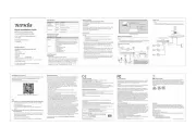
The switch supports auto MDI/MDIX. You can use either a straight through cable
or a crossover cable to connect the switch to Ethernet devices.
− Desktop mounting: ESD bracelet or gloves
− Wall mounting: ESD bracelet or gloves, screwdriver, spirit level, marker,
hammer drill, rubber hammer, ladder, 2 plastic anchors (self-prepared
except TEG1016M/TEG1116M, height: 6.6 mm, inner diameter: 2.4 mm,
length: 26.4 mm) and 2 screws (self-prepared except TEG1016M/TEG1116M,
thread diameter: 3 mm, length: 14 mm, head diameter: 5.2 mm)
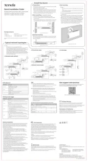
Typical network topologies
Horizontally place the switch right-side up on a big enough, clean, stable and
After connection, you can check whether the switch is connected properly or
change its working mode based on the following tables.
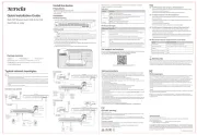
1. Mark your wall for the wall-mounting slots on the bottom of the switch
and drill two holes (diameter: 6 mm) horizontally. The distance between
two holes varies with models (TEG1008M/TEF1109D: 116 mm, TEG1005D/
TEF1005D/TEG1005M: 80 mm, TEG1016M/TEG1116M: 110 mm).
2. Hammer plastic anchors into the holes.
3. Insert screws into the plastic anchors, leaving a gap (at least 2.5 mm)
between the screw heads and plastic anchors.
4.Place the switch on the screws and slide it down until it locks into place.
V1.3 Keep for future reference
NOMBRE DEL PRODUCTO: Switch de Gigabit Ethernet de
MODELO: TEG1005D/TEG1005M/TEG1008M/TEG1016M/
100-240 V ca 50/60 Hz, 0.3 A (TEG1005D/TEG1005M/
100-240 V ca 50/60 Hz, 0.4 A (TEG1016M/TEG1116M)
5 V cc 0.6 A (TEG1005D/TEG1005M/TEG1008M)
12 V cc 1.0 A (TEG1016M/TEG1116M)
NOMBRE DEL PRODUCTO: Switch de desktop Ethernet
Alimentación: 100-240 V ca 50/60 Hz, 0.3 A
NOMBRE DEL PRODUCTO: Switch Fast Ethernet de 5 portas
Alimentación: 100-240 V ca 50/60 Hz, 0.3 A