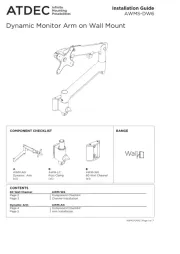
Atdec TH-AN-CM Manual
Læs gratis den danske manual til Atdec TH-AN-CM (2 sider) i kategorien Flad panel støtte. Denne vejledning er vurderet som hjælpsom af 15 personer og har en gennemsnitlig bedømmelse på 4.1 stjerner ud af 8 anmeldelser.
Har du et spørgsmål om Atdec TH-AN-CM, eller vil du spørge andre brugere om produktet?
Produkt Specifikationer
| Mærke: | Atdec |
| Kategori: | Flad panel støtte |
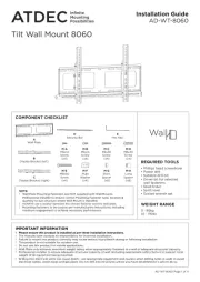
| Model: | TH-AN-CM |
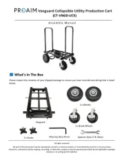
| Bredde: | 116 mm |
| Dybde: | 28 mm |
| Højde: | 1096 mm |
| Produktfarve: | Sølv |
| Husmateriale: | Aluminium |
| Monteringstype: | Væg |
| Vægt (efter britisk standard): | 176 Pund |
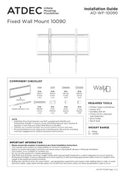
| Vægt (maks.): | 80 kg |
Har du brug for hjælp?
Hvis du har brug for hjælp til Atdec TH-AN-CM stil et spørgsmål nedenfor, og andre brugere vil svare dig
Flad panel støtte Atdec Manualer


Flad panel støtte Manualer
- GPX
- Da-Lite
- One For All
- Zaor
- Ultimate
- NewStar
- Ewent
- StarTech.com
- BakkerElkhuizen
- BlueBuilt
- Rocstor
- Konig & Meyer
- Fellowes
- Nabo
- Monoprice
Nyeste Flad panel støtte Manualer