Manufacturer reserves the right to discontinue, or change at any time, specifications or designs without notice and without incurring obligations.
Catalog No. 04-53300144-01 Printed in U.S.A. Form 30XW-9SI Rev. A Pg 1 5-21 Replaces: 30XW-8SI
Installation Instructions
CONTENTS
Page
SAFETY CONSIDERATIONS . . . . . . . . . . . . . . . . . . . . . .1
INTRODUCTION . . . . . . . . . . . . . . . . . . . . . . . . . . . . . . . . . .2
System Design . . . . . . . . . . . . . . . . . . . . . . . . . . . . . . . . . . .2
• SYSTEM PIPING
• MINIMUM LOOP VOLUME
INSTALLATION . . . . . . . . . . . . . . . . . . . . . . . . . . . . . . . . . .2
Step 1 — Inspect Shipment . . . . . . . . . . . . . . . . . . . . . . .2
Step 2 — Prepare Installation Site . . . . . . . . . . . . . . . .2
Step 3 — Rig and Place Unit . . . . . . . . . . . . . . . . . . . . .24
Step 4 — Connect Piping . . . . . . . . . . . . . . . . . . . . . . . .25
• EVAPORATOR FLUID, CONDENSER FLUID, VENT,
AND DRAIN PIPING
• CONDENSER FLUID CONTROL VALVE
• INSTALL PRESSURE RELIEF REFRIGERANT VENT
PIPING
• FILL FLUID LOOP
• WATER TREATMENT
• BRINE UNITS
• PREPARATION FOR YEAR-ROUND OPERATION
• DUAL CHILLER CONTROL
Step 5 — Make Electrical Connections. . . . . . . . . . .33
• FIELD POWER CONNECTIONS
• FIELD CONTROL POWER CONNECTIONS
• EVAPORATOR PUMP CONTROL
• CONDENSER PUMP CONTROL
• CARRIER COMFORT NETWORK
®
COMMUNICATION
BUS WIRING
• BACNET COMMUNICATION OPTION WIRING
• NON-CCN COMMUNICATION WIRING
• FIELD CONTROL OPTION WIRING
Step 6 — Install Accessories . . . . . . . . . . . . . . . . . . . .43
• ENERGY MANAGEMENT MODULE
• REMOTE ENHANCED DISPLAY (OR TOUCH PILOT™
DISPLAY)
• CONTROL ACCESSORIES
• MISCELLANEOUS ACCESSORIES
Step 7 — Leak Test Unit . . . . . . . . . . . . . . . . . . . . . . . . .43
Step 8 — Charge Unit . . . . . . . . . . . . . . . . . . . . . . . . . . . .43
Step 9 — Install Field Insulation and Lagging . . . .44
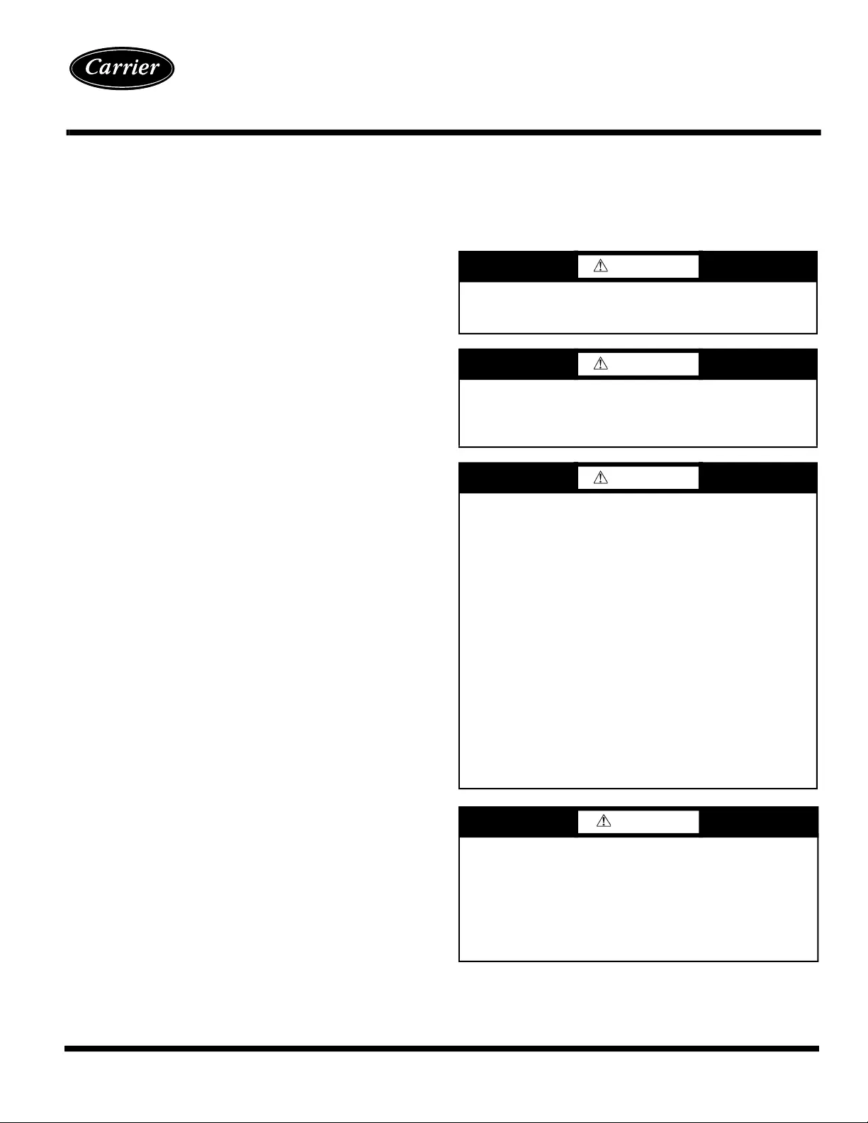
SAFETY CONSIDERATIONS
Installation and servicing of air-conditioning equipment can be
hazardous due to system pressure and electrical components. Only
trained and qualified service personnel should install, repair, or
service air-conditioning equipment.
Untrained personnel can perform basic maintenance functions of
cleaning coils and filters and replacing filters. All other operations
should be performed by trained service personnel. When working
on air-conditioning equipment, observe precautions in the litera-
ture, tags and labels attached to the unit, and other safety precau-
tions that may apply.
Follow all safety codes, including ANSI (American National Stan-
dards Institute) Z223.1. Wear safety glasses and work gloves. Use
quenching cloth for unbrazing operations. Have fire extinguisher
available for all brazing operations.
0
WARNING
Before performing service or maintenance operations on unit,
turn off main power switch to unit. Electrical shock could
cause personal injury.
WARNING
Improper installation, adjustment, alteration, service, or main-
tenance can cause injury or property damage. Refer to this
manual. For assistance or additional information, consult a
qualified installer, service agency, or the gas supplier.
WARNING
DO NOT USE TORCH to remove any component. System
contains oil and refrigerant under pressure.
To remove a component, wear protective gloves and goggles
and proceed as follows:
a. Shut off electrical power to unit.
b. Recover refrigerant to relieve all pressure from system
using both high-pressure and low pressure ports.
c. Traces of vapor should be displaced with nitrogen and
the work area should be well ventilated. Refrigerant in
contact with an open flame produces toxic gases.
d. Cut component connection tubing with tubing cutter and
remove component from unit. Use a pan to catch any oil
that may come out of the lines and as a gage for how
much oil to add to the system.
e. Carefully unsweat remaining tubing stubs when neces-
sary. Oil can ignite when exposed to torch flame.
Failure to follow these procedures may result in personal
injury or death.
CAUTION
DO NOT re-use compressor oil or any oil that has been
exposed to the atmosphere. Dispose of oil per local codes and
regulations. DO NOT leave refrigerant system open to air any
longer than the actual time required to service the equipment.
Seal circuits being serviced and charge with dry nitrogen to
prevent oil contamination when timely repairs cannot be com-
pleted. Failure to follow these procedures may result in dam-
age to equipment.
AquaForce
®
30XW150-400
Water-Cooled Liquid Chillers