Carrier PremierLink 33CSPREMLK Manual

Carrier Klimaanlæg PremierLink 33CSPREMLK

Læs gratis den danske manual til Carrier PremierLink 33CSPREMLK (60 sider) i kategorien Klimaanlæg. Denne vejledning er vurderet som hjælpsom af 6 personer og har en gennemsnitlig bedømmelse på 4.4 stjerner ud af 3.5 anmeldelser. Har du et spørgsmål om Carrier PremierLink 33CSPREMLK, eller vil du spørge andre brugere om produktet?

Side 1/60
Manufacturer reserves the right to discontinue, or change at any time, specifications or designs without notice and without incurring obligations.
Catalog No. 04-53330016-01 Printed in U.S.A. Form 33CS-68SI Pg 1 5-11 Replaces: 33CS-67SI
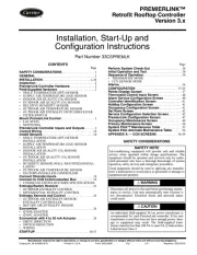
Installation, Start-Up and
Configuration Instructions
Part Number 33CSPREMLK
CONTENTS
Page
SAFETY CONSIDERATIONS. . . . . . . . . . . . . . . . . . . . . . 1
GENERAL . . . . . . . . . . . . . . . . . . . . . . . . . . . . . . . . . . . . . . . . 2
INSTALLATION . . . . . . . . . . . . . . . . . . . . . . . . . . . . . . . . 2-30
Inspection. . . . . . . . . . . . . . . . . . . . . . . . . . . . . . . . . . . . . . . . 2
PremierLink Controller Hardware. . . . . . . . . . . . . . . . . 2
Field-Supplied Hardware . . . . . . . . . . . . . . . . . . . . . . . . . 2
SPACE TEMPERATURE (SPT) SENSOR
SUPPLY AIR TEMPERATURE (SAT) SENSOR
INDOOR AIR QUALITY CO
2
SENSOR
OUTDOOR AIR QUALITY CO
2
SENSOR
RELATIVE HUMIDITY SENSOR
OUTDOOR AIR TEMPERATURE SENSOR
OUTDOOR AIR ENTHALPY SWITCH/RECEIVER
FILTER SWITCH
Mount PremierLink Control. . . . . . . . . . . . . . . . . . . . . . . 3
•LOCATION
MOUNTING
PremierLink Controller Inputs and Outputs . . . . . . 3
Control Wiring. . . . . . . . . . . . . . . . . . . . . . . . . . . . . . . . . . . 10
Install Sensors . . . . . . . . . . . . . . . . . . . . . . . . . . . . . . . . . . 10
SPACE TEMPERATURE (SPT) SENSOR
INSTALLATION
SUPPLY AIR TEMPERATURE (SAT) SENSOR
INSTALLATION
INDOOR AIR QUALITY CO
2
SENSOR
INSTALLATION
OUTDOOR AIR QUALITY CO
2
SENSOR
INSTALLATION
HUMIDITY SENSOR (WALL-MOUNTED) INSTAL-
LATION
OUTDOOR AIR TEMPERATURE SENSOR
FACTORY-INSTALLED CONTROLLER
Connect Discrete Inputs . . . . . . . . . . . . . . . . . . . . . . . . 19
Connect to CCN Communication Bus . . . . . . . . . . . 19
COMMUNICATIONS BUS WIRE SPECIFICATIONS
Enthalpy/Switch Receiver . . . . . . . . . . . . . . . . . . . . . . . 23
OUTDOOR ENTHALPY CONTROL
•DIFFERENTIAL ENTHALPY CONTROL
Enthalpy Sensors and Control . . . . . . . . . . . . . . . . . . 25
OUTDOOR AIR ENTHALPY SENSOR/
ENTHALPY CONTROLLER
RETURN AIR ENTHALPY SENSOR
Economizer . . . . . . . . . . . . . . . . . . . . . . . . . . . . . . . . . . . . . 26
Q769B ADAPTER
Q769C ADAPTER
Economizer with 4 to 20 mA Actuator . . . . . . . . . . . 28
DRIVE DIRECTION
SWITCH SELECTION
•WIRING
START-UP . . . . . . . . . . . . . . . . . . . . . . . . . . . . . . . . . . . . 30-37
Page
Perform System Check-Out . . . . . . . . . . . . . . . . . . . . . 30
Initial Operation and Test . . . . . . . . . . . . . . . . . . . . . . . 30
Sequence of Operation. . . . . . . . . . . . . . . . . . . . . . . . . . 30
THERMOSTAT MODE
CCN SENSOR MODE
Alarms . . . . . . . . . . . . . . . . . . . . . . . . . . . . . . . . . . . . . . . . . . 36
CONFIGURATION . . . . . . . . . . . . . . . . . . . . . . . . . . . . 37-55
Points Display Screen. . . . . . . . . . . . . . . . . . . . . . . . . . . 37
Thermostat Control Input Screen. . . . . . . . . . . . . . . . 40
Alarm Service Configuration Screen . . . . . . . . . . . . 40
Controller Identification Screen . . . . . . . . . . . . . . . . . 41
Holiday Configuration Screen . . . . . . . . . . . . . . . . . . . 41
Occupancy Configuration Screen . . . . . . . . . . . . . . . 41
Set Point Screen . . . . . . . . . . . . . . . . . . . . . . . . . . . . . . . . 42
Service Configuration Selection Screen. . . . . . . . . 43
PremierLink Configuration Screen . . . . . . . . . . . . . . 47
Occupancy Maintenance Screen . . . . . . . . . . . . . . . . 49
Primary Maintenance Screen. . . . . . . . . . . . . . . . . . . . 50
System Pilot™ Maintenance Table . . . . . . . . . . . . . . 53
System Pilot Alternate Maintenance Table. . . . . . . 54
APPENDIX A — CCN SCREENS . . . . . . . . . . . . . . 56-59
SAFETY CONSIDERATIONS
SAFETY NOTE
Air-conditioning equipment will provide safe and reliable
service when operated within design specifications. The
equipment should be operated and serviced only by autho-
rized personnel who have a thorough knowledge of system
operation, safety devices and emergency procedures.
Good judgement should be used in applying any manufac-
turers instructions to avoid injury to personnel or damage to
equipment and property.
WARNING
Disconnect all power to the unit before performing mainte-
nance or service. Unit may automatically start if power is
not disconnected. Electrical shock and personal injury
could result.
CAUTION
An individual field-supplied 24-vac power transformer is
recommended for each PremierLink controller. If the unit
transformer is used but does not have enough power, dam-
age to equipment may result. The field-supplied trans-
former must be less than 100 VA to meet UL (Underwriters
Laboratories) Class 2.
PREMIERLINK™
Retrofit Rooftop Controller
Version 3.x
2
GENERAL
The PremierLink™ controller, version 3.x, is a field retrofit
rooftop control compatible with the Carrier Comfort Network
®
(CCN) system. This control is designed to allow users the ac-
cess and ability to change factory-defined settings, thus ex-
panding the function of the standard unit control board. The
complete PremierLink package (part number 33CSPREMLK)
consists of a rooftop control circuit board with plastic cover
and label, wire harnesses, spade connectors, wire nuts and 4
mounting screws.
Access is available via an RJ-11 connection or a 3-wire con-
nection to the communication bus. User interfaces available for
use with the CCN system are PCs equipped with Carrier user
interface software such as Service Tool, ComfortVIEW
, or
ComfortWORKS
®
software. When used as part of the CCN
system, other devices such as the CCN data transfer, System
Pilot™, Touch Pilot™, or Comfort Controller can read data
from or write data to the PremierLink retrofit controller. The
PremierLink controller default address is 0,31.
The PremierLink controller is available as a factory-
installed option on some units. Additional terminal board(s) are
provided for field wiring. Sensors and input devices added in
the field should be wired to the terminal board(s) instead of di-
rectly to the PremierLink controller. Refer to the unit installa-
tion and service manuals for terminal locations and details. For
typical factory wiring details, see Factory-Installed Controller
section on page 19. Refer to unit’s label wiring diagram for
specific unit wiring.
INSTALLATION
Inspection —
Inspect package contents for visual defects
that may have occurred during shipping. If there is any dam-
age, contact your local representative before proceeding.
PremierLink Controller Hardware — The Premier-
Link package consists of the following hardware:
control module (with plastic cover and label)
7 wire harnesses
10 spade connectors
wire nuts
4 no. 6x1-in. self-drilling Phillips pan head mounting
screws
Field-Supplied Hardware — The PremierLink con-
troller is configurable with the following field-supplied
sensors:
space temperature sensor (33ZCT55SPT, 33ZCT56SPT,
33ZCT59SPT, or 33PILOT-01) in sensor mode or thermo-
stat mode for economizer control
supply air temperature sensor (33ZCSENSAT) required for
all applications
indoor air quality sensor (33ZCSENCO2, 33ZCT55CO2,
33ZCT56CO2) required only for demand control
ventilation. A dedicated 24-vac transformer is required.
outdoor air quality sensor (33ZCTSENCO2) required only
for demand control ventilation
outdoor air temperature sensor (33ZCSENOAT)
outdoor air enthalpy switch (33CSENTHSW)
filter switch (third party differential airflow)
return air enthalpy sensor (33CSENTSEN)
indoor relative humidity sensor (33ZCSENSRH-01),
required only for dehumidification
For specific details about sensors, refer to the literature
supplied with the sensor.
SPACE TEMPERATURE (SPT) SENSOR — A field-
supplied Carrier space temperature sensor is required to maintain
space temperature in sensor mode. There are four sensors avail-
able for this application:
33ZCT55SPT, space temperature sensor with override
button
33ZCT56SPT, space temperature sensor with override
button and set point adjustment
33ZCT59SPT, space temperature sensor with LCD (liquid
crystal display) screen, override button, and set point
adjustment
33PILOT-01, System Pilot communicating room sensor
with LCD display screen, override button, setpoint adjust-
ment, temperature and setpoint display and system time
clock
If controlling an economizer in the thermostat mode, a duct
sensor must be mounted in the return air duct and wired to SPT
input.
SUPPLY AIR TEMPERATURE (SAT) SENSOR — The
PremierLink controller must be connected to a field-supplied
supply air temperature (SAT) sensor (part number
33ZCSENSAT) to monitor the temperature of the air delivered.
The SAT consists of a thermistor encased within a stainless
steel probe. The probe is 6 in. nominal length. The SAT sensor
has 114 in. of unshielded, plenum-rated cable (2 conductors,
22 AWG [American Wire Gage]). The sensor range is –40 to
185 F with a nominal resistance of 10,000 ohms at 77 F. The
sensor measures temperature with an accuracy of ±0.36 F.
Ideally, the SAT sensor should be located inside the unit
under the heat exchanger. The SAT sensor can also be installed
in the supply air duct downstream from unit heat source to
control.
INDOOR AIR QUALITY CO
2
SENSOR An indoor air
quality sensor is required for CO
2
level monitoring. Three
different CO
2
sensors are available for this application:
33ZCSENCO2 sensor is an indoor, wall-mounted sensor
with an LCD (liquid-crystal display) screen
33ZCT55CO2 sensor is an indoor, wall-mounted sensor
without display. The CO
2
sensor also includes a space tem-
perature sensor with override button
33ZCT56CO2 sensor is an indoor, wall-mounted sensor
without display. The CO
2
sensor also includes a space tem-
perature sensor with override button and temperature offset
OUTDOOR AIR QUALITY CO
2
SENSOR — The
outdoor air CO
2
sensor (33ZCSENCO2) is designed to moni-
tor carbon dioxide (CO
2
) levels found in diesel exhaust and
control ventilation systems. It comes with an outdoor enclo-
sure. This sensor provides an outdoor baseline for differential
DCV (demand controlled ventilation) control.
NOTE: The relative humidity sensor and the outdoor air CO
2
sensor cannot both be used on the controller at the same time.
RELATIVE HUMIDITY SENSOR — The 33ZCSENSRH-
01 relative space humidity sensor is required for dehumidifica-
tion control on a rooftop unit equipped with a dehumidification
device. Otherwise, the relative humidity sensor is used for
monitoring only.
NOTE: The relative humidity sensor and the outdoor air CO
2
sensor cannot both be used on the controller at the same time.
OUTDOOR AIR TEMPERATURE SENSOR — The
outdoor air temperature sensor (33ZCSENOAT) monitors the
temperature of the outside air. If the sensor is to be installed in
the outdoor air duct instead of an outdoor location, sensor
33ZCSENPAT should be used.
OUTDOOR AIR ENTHALPY SWITCH/RECEIVER
(33CSENTHSW) This device measures both temperature
and humidity and converts the data into a relay output depen-
dent on the sensor mode. Mode 1 is designed to energize the
relay at a fixed set point of 28 Btu/lb or 75 F. Mode 2 is used in
IMPORTANT: PremierLink part number 33CSPREMLK
should only be used in applications where the integrity
of the Underwriters Laboratories rating will be
maintained.


Produkt Specifikationer

Mærke: Carrier
Kategori: Klimaanlæg
Model: PremierLink 33CSPREMLK

Har du brug for hjælp?

Hvis du har brug for hjælp til Carrier PremierLink 33CSPREMLK stil et spørgsmål nedenfor, og andre brugere vil svare dig