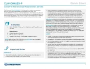
Crestron CLW-DIMEX-P Manual

| Mærke: | Crestron |
| Kategori: | Lysdæmper |
| Model: | CLW-DIMEX-P |
| Type: | Lysdæmper |
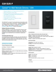
| Bredde: | 44 mm |
| Dybde: | 44 mm |
| Højde: | 105 mm |
| Relativ luftfugtighed ved drift (H-H): | 10 - 90 % |
| Driftstemperatur (T-T): | 0 - 40 °C |
| RF-transmissionsfrekvens: | 2400 MHz |
Har du brug for hjælp?
Hvis du har brug for hjælp til Crestron CLW-DIMEX-P stil et spørgsmål nedenfor, og andre brugere vil svare dig
Lysdæmper Crestron Manualer

3 December 2025

13 August 2025
13 August 2025
13 August 2025
13 August 2025

13 August 2025

13 August 2025
9 Juli 2025
9 Juli 2025
9 Juli 2025
Lysdæmper Manualer
Nyeste Lysdæmper Manualer

23 December 2025

15 December 2025

11 December 2025

9 December 2025

9 December 2025

9 December 2025
17 November 2025
9 November 2025
7 Oktober 2025
27 September 2025