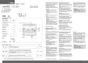
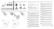
Hager TXA661A Manual

| Mærke: | Hager |
| Kategori: | Lysdæmper |
| Model: | TXA661A |
| Kode for international beskyttelse (IP): | IP20 |
| Produktfarve: | Grå |
| Driftstemperatur (T-T): | -5 - 45 °C |
| Antal produkter inkluderet: | 1 stk |
Har du brug for hjælp?
Hvis du har brug for hjælp til Hager TXA661A stil et spørgsmål nedenfor, og andre brugere vil svare dig
Lysdæmper Hager Manualer
9 August 2025

9 December 2024

1 August 2024

1 August 2024

1 August 2023

4 Marts 2023

15 November 2022
Lysdæmper Manualer
- VAMA
- AMX
- Sonoro
- TP-Link
- Trust
- Handson
- BeamZ
- Cotech
- Berker
- Legrand
- Mercury
- Chauvet
- Kopp
- Velbus
- Eminent
Nyeste Lysdæmper Manualer
7 Oktober 2025
27 September 2025

26 September 2025
15 September 2025

14 September 2025

14 September 2025

30 August 2025
27 August 2025
26 August 2025
26 August 2025