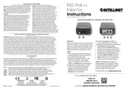
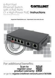
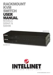
Intellinet 560641 Manual
Læs gratis den danske manual til Intellinet 560641 (12 sider) i kategorien Skifte. Denne vejledning er vurderet som hjælpsom af 6 personer og har en gennemsnitlig bedømmelse på 4.7 stjerner ud af 3.5 anmeldelser.
Har du et spørgsmål om Intellinet 560641, eller vil du spørge andre brugere om produktet?
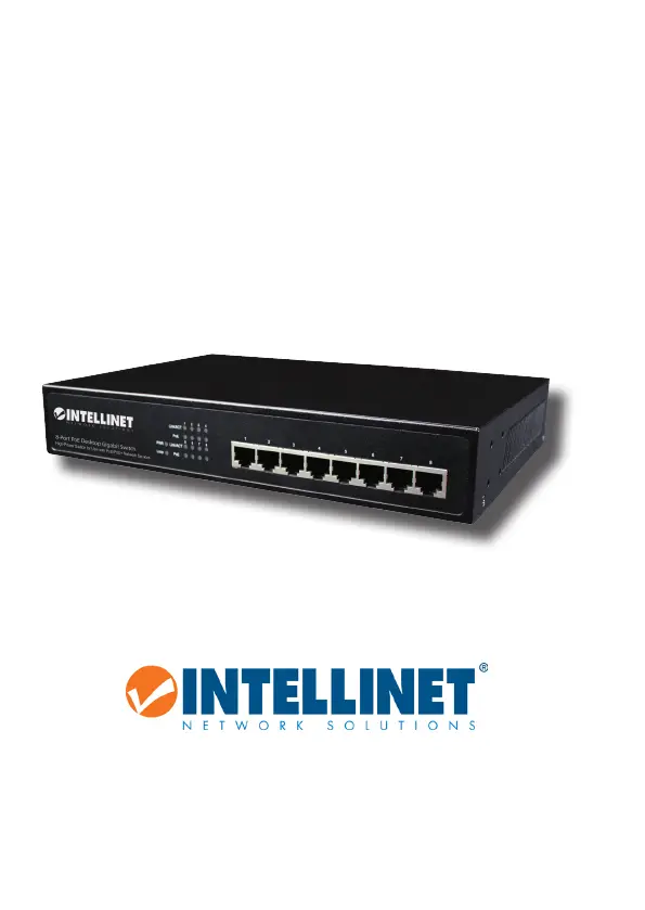
Produkt Specifikationer
| Mærke: | Intellinet |
| Kategori: | Skifte |
| Model: | 560641 |
| Vekselstrømsindgangsspænding: | 100 - 240 V |
| Vekselstrømsindgangsfrekvens: | 50 - 60 Hz |
| Bredde: | 280 mm |
| Dybde: | 180 mm |
| Højde: | 44 mm |
| Vægt: | 2000 g |
| Brugervejledning: | Ja |
| Produktfarve: | Sort |
| Opbevaringstemperatur (T-T): | -20 - 70 °C |
| Relativ luftfugtighed ved drift (H-H): | 10 - 90 % |
| Driftstemperatur (T-T): | 0 - 40 °C |
| Husmateriale: | Metal |
| Kabler inkluderet: | Vekselstrøm |
| Strømkilde: | Vekselstrøm |
| Certificering: | FCC Class B, VCCI Class B, CE, RoHS, EN 60950-1 |
| Strømforbrug (maks.): | 150 W |
| Netværksstandarder: | IEEE 802.3, IEEE 802.3ab, IEEE 802.3af, IEEE 802.3at, IEEE 802.3az, IEEE 802.3u, IEEE 802.3x |
| LED-indikatorer: | Ja |
| Harmoniseret systemkode (HS): | 85176990 |
| Strøm-LED: | Ja |
| Fuld duplex: | Ja |
| Strøm over Ethernet (PoE): | Ja |
| 10G understøttelse: | Ingen |
| Kobber ethernet kabelteknologi: | 1000BASE-T, 100BASE-TX, 10BASE-T |
| Basis omskiftning RJ-45 Ethernet porte, antal: | 8 |
| Basis omskiftning RJ-45 Ethernet porttype: | Gigabit Ethernet (10/100/1000) |
| Opbevar-og-frem: | Ja |
| MAC adresselabel: | 8000 entries |
| Switch kapacitet: | 16 Gbit/sek. |
| Stativ-montering: | Ja |
| Strømstik: | DC-in-stik |
| Pakke bufferlager: | 256 MB |
Har du brug for hjælp?
Hvis du har brug for hjælp til Intellinet 560641 stil et spørgsmål nedenfor, og andre brugere vil svare dig
Skifte Intellinet Manualer


Skifte Manualer
- ATen
- Avocent
- Victron Energy
- Ebode
- Intermatic
- EVE
- Kemo
- Homematic IP
- PCE
- ConnectPro
- Pyle
- Triax
- Chacon
- QNAP
- Perel
Nyeste Skifte Manualer