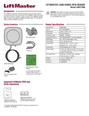
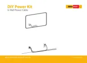
LiftMaster 041-0347-000 Manual


Læs gratis den danske manual til LiftMaster 041-0347-000 (4 sider) i kategorien Ikke kategoriseret. Denne vejledning er vurderet som hjælpsom af 19 personer og har en gennemsnitlig bedømmelse på 3.6 stjerner ud af 10 anmeldelser. Har du et spørgsmål om LiftMaster 041-0347-000, eller vil du spørge andre brugere om produktet?

Side 1/4
11.
Locate the notch
in the camera’s
opener and
pull down.
12.
Follow the myQ®
App instructions
to add the new
camera to your
myQ® account.
10.
Reattach the
newbadge.
Reconnect
power and
battery, if used.
3.
Using a flat head
screwdriver,remove the
badge at the opener’s
bottom.
Badge is held in by four
clips, pull badge off.
Badge
9.
Align screw
holes and place
camera into
garage door
opener.
Fasten the
three screws
with a Phillips
screwdriver.
To prevent damage to the camera,
push the camera lens closed when
replacing, and hold it in place as
you remove securing hardware.
DO NOT touch the camera logic
board during installation.
ALWAYS wear protective gloves
and eye protection when changing
the battery or working around the
battery compartment.
Introduction
Installation
CAMERA SERVICE KIT REPLACEMENT
Model 041-0347-000
Your camera is accessible at the opener’s bottom side. After installing
the new camera, use your myQ® app to connect your new camera to
your myQ® account.
2.
Disconnect
power to the
garage door
opener, and
remove the
backup battery,
if used.
1.
Using the myQ app,
delete the garage
door opener from
the myQ account
before re-adding the
opener and camera
to the myQ account.
To prevent possible
SERIOUS INJURY or DEATH:
Disconnect ALL electric
and battery power BEFORE
performing ANY service or
maintenance.
WARNING: This
product can
expose you to
chemicals including lead,
which are known to the
State of California to cause
cancer or birth defects or
other reproductive harm.
For more information go to
www.P65Warnings.ca.gov.
Camera LED Status Indicators
WHAT YOU SEE WHAT IT MEANS
Solid White Camera is powering up.
Flashing Blue Ready to be set up in the myQ
® App.
Solid Blue Connected to your mobile device. You are not yet connected to the Internet. If this
persists after setup, check your home router and Internet. Connecting to Wi-Fi
® and
connecting to the myQ
® App.
Flashing Blue and Green Connecting to Wi-Fi and connecting to the myQ
® App.
Solid Green Connected to the myQ
® App.
Flashing Purple Receiving firmware updates.
Solid Red Camera thermal error state when the camera reaches high heat 60 °C temperature
and cools down.
Tools:
Phillips Screwdriver
Flat head Screwdriver
Ladder
Masking Tape (optional)
Hardware:
Screw Qty. (3)
Decorative Badge
Camera
NOTICE: This device complies with part 15 of the FCC rules and
Innovation, Science and Economic Development Canada licence-exempt
RSSs. Operation is subject to the following two conditions: (1) this device
may not cause harmful interference, and (2) this device must accept any
interference received, including interference that may cause undesired
operation. Any changes or modications not expressly approved by the
party responsible for compliance could void the user’s authority to operate
the equipment.
This device must be installed to ensure a minimum 20 cm (8 in.) distance
is maintained between users/bystanders and device.
This device has been tested and found to comply with the limits for a Class
B digital device, pursuant to part 15 of the FCC rules and Industry Canada
ICES standard. These limits are designed to provide reasonable protection
against harmful interference in a residential installation. This equipment
generates, uses and can radiate radio frequency energy and, if not
installed and used in accordance with the instructions, may cause harmful
interference to radio communications.
However, there is no guarantee that interference will not occur in a
particular installation. If this equipment does cause harmful interference
to radio or television reception, which can be determined by turning
the equipment off and on, the user is encouraged to try to correct the
interference by one or more of the following measures:
• Reorient or relocate the receiving antenna.
• Increase the separation between the equipment and receiver.
• Connect the equipment into an outlet on a circuit different from that to
which the receiver is connected.
• Consult the dealer or an experienced radio/TV technician for help.
The device for operation in the band 5150-5250 MHz is only for indoor
use to reduce the potential for harmful interference to co-channel mobile
satellite systems.
6.
Open camera
and remove the
three-pronged wire
harness that has
the black, green,
and white wires.
Rotate the
connector clip
backward before
removing the wire
harness.
Connector clip
7.
Open new camera
and place the
three-pronged wire
harness that has the
black, green, and
white wires.
Rotate connector
clip back into place
after reconnection.
Close camera.
5.
Remove the
two-pronged wire
harness with the
black and
white wires.
4.
Unscrew the
camera slowly
from the opener
housing by
removing the
three screws
with a Phillips
screwdriver.
TIP: Use masking tape to
hold the camera in place
as you remove screws.
Masking
Tape
8.
Connect the
two-pronged
wire harness
that has the
black and
white wires.
Para evitar daños a la cámara,
cierre el lente de la cámara cuando
la reemplace, y sosténgala en
el lugar al retirar los herrajes de
seguridad. NO toque el tablero
lógico de la cámara durante la
instalación.
Use SIEMPRE guantes protectores
y protección para la vista al
cambiar la batería o al trabajar
cerca del compartimiento de la
batería.
Introducción
Instalación
JUEGO DE SERVICIO DE LA CÁMARA DE REPUESTO
Modelo 041-0347-000
Se puede acceder a la cámara desde el lado inferior del abre-puertas.
Una vez instalada la cámara nueva, use la aplicación myQ
® para conectar
la cámara a su cuenta myQ®.
Para evitar posibles LESIONES
GRAVES o la MUERTE:
Desconecte TOTALMENTE
la corriente eléctrica y de la
batería ANTES de realizar
CUALQUIER servicio o
mantenimiento.
Indicadores de estado del LED de la cámara
LO QUE USTED VE LO QUE SIGNIFICA
Blanco sin parpadear La cámara se está encendiendo.
Azul parpadeante Preparada para congurarla en la aplicación myQ
®.
Azul sin parpadear Conectada a su dispositivo móvil. Usted no está conectado a Internet. Si esto
persiste después de la conguración, revise el router y la conexión a Internet de su
casa. Conectándose a la red de Wi-Fi
® y a la aplicación myQ
®.
Azul y verde parpadeante Conectándose a la red de Wi-Fi y a la aplicación myQ
®.
Verde sin parpadear Conectada a la aplicación myQ
®.
Púrpura parpadeante Recibiendo actualizaciones de rmware.
Rojo sin parpadear El estado de error térmico de la cámara ocurre cuando la cámara alcanza una alta
temperatura de 60 °C y se enfría.
Herramientas:
Destornillador estrella
Destornillador de cabeza plana
Escalera
Cinta adhesiva de papel (opcional)
Accesorios de montaje:
Cant. de tornillos (3)
Insignia decorativa
Cámara
AVISO: Este dispositivo cumple con la parte 15 de la reglamentación de
la FCC y los estándares RSS exentos de licencia de Innovación, Ciencia
y Desarrollo Económico de Canadá. La operación está sujeta a las dos
condiciones siguientes:(1) este dispositivo no puede causar interferencia
perjudicial, y (2) este dispositivo debe aceptar cualquier interferencia
recibida, incluyendo la interferencia que puede causar una operación no
deseable.
Cualquier cambio o modicación no expresamente aprobada por la parte
responsable del cumplimiento podría anular la autoridad del usuario para
operar el equipo.
Instalar este dispositivo de manera que quede una distancia mínima de 20
cm (8 pulg.) entre el dispositivo y los usuarios/transeúntes.
Este equipo p2-ha sido vericado y cumple con los límites para un dispositivo
digital de Clase B, conforme con la Parte 15 de las normas de la FCC y
el estándar ICES de Industry Canada. Estos límites se establecen para
brindar un nivel razonable de protección contra interferencias perjudiciales
en instalaciones residenciales. Este equipo genera, usa y puede emitir
energía de radiofrecuencia. Si no se instala y utiliza de acuerdo con las
instrucciones podrá causar interferencia con comunicaciones radiales.
Aun así, no hay garantía de que no se produzcan interferencias en una
instalación particular. Si este equipo produce interferencia en la recepción
de radio o televisión, lo cual puede determinarse apagando y encendiendo
la unidad, el usuario debe tratar de corregir el problema por medio de lo
siguiente:
Volver a orientar o reubicar la antena receptora.
Aumentar la distancia entre el equipo y el receptor.
Conectar el equipo en una salida de un circuito distinto del circuito al que
está conectado el receptor.
Consultar con el distribuidor o con un técnico de radio/TV experimentado
para pedir ayuda.
El dispositivo para el funcionamiento en la banda 5150-5250 MHz es
solamente para uso en interiores a n de reducir posibles interferencias
perjudiciales a los sistemas móviles por satélite de canal común.
ADVERTENCIA:
Este producto
puede exponerle
a productos químicos
(incluido el plomo), que a
consideración del estado de
California causan cáncer,
defectos congénitos u otros
daños reproductivos. Para
más información, visite
www.P65Warnings.ca.gov
11.
Localice la muesca
en el abridor de
la cámara y tire
hacia abajo.
12.
Follow the
myQ
® Siga las
instrucciones de la
aplicación myQ
®
para agregar la
cámara nueva a su
cuenta myQ
®.
10.
Vuelva a
colocar
la nueva
insignia.
Vuelva a
conectar la
alimentación
y la batería,
si se utilizan.
3.
Con un destornillador
de cabeza plana, retire
la insignia en
la parte inferior
del abridor.
La insignia se sujeta
con cuatro presillas.
Quite la insignia.
Insignia
9.
Alinee los
oricios de los
tornillos
y coloque
la cámara en el
abrepuertas
de garage.
Ajuste los tres
tornillos con un
destornillador
Phillips.
2.
Desconecte la
alimentación
del abrepuertas
degarage y
retire la batería
de respaldo, si
se utiliza.
1.
Mediante la aplicación
myQ, elimine el
abrepuertas de garaje
de la cuenta myQ antes
de volver a añadir
el abrepuertas y la
cámara a dicha cuenta.
6.
Abra la cámara
y retire el arnés
del cable de tres
puntas que tiene
los cables negro,
verde y blanco.
Gire la presilla del
conector hacia
atrás antes de
retirar el arnés de
cables.
Presilla del conector
7.
Abra la nueva cámara
y coloque el arnés del
cable de tres puntas
que tiene los cables
negro, verde y blanco.
Vuelva a girar la
presilla del conector
a su lugar de origen
después de la
reconexión.
Cierre la cámara.
5.
Retire el arnés
del cable de
dos puntas
que tiene los
cables negro
y blanco.
4.
Extraiga lentamente
lacámara de
la carcasa del
abridor al
retirar los tres
tornillos con un
destornillador
Phillips.
CONSEJO: use cinta
adhesiva para mantener
la cámara en su lugar mientras
retira los tornillos.
Cinta adhesiva
de papel
8.
Conecte el arnés
del cable de dos
puntas que tiene
los cables
negro y
blanco.


Produkt Specifikationer

Mærke: LiftMaster
Kategori: Ikke kategoriseret
Model: 041-0347-000

Har du brug for hjælp?

Hvis du har brug for hjælp til LiftMaster 041-0347-000 stil et spørgsmål nedenfor, og andre brugere vil svare dig


Ikke kategoriseret LiftMaster Manualer

Ikke kategoriseret Manualer

Nyeste Ikke kategoriseret Manualer