Nexa AN-179 Manual
| Mærke: | Nexa |
| Kategori: | Modtager |
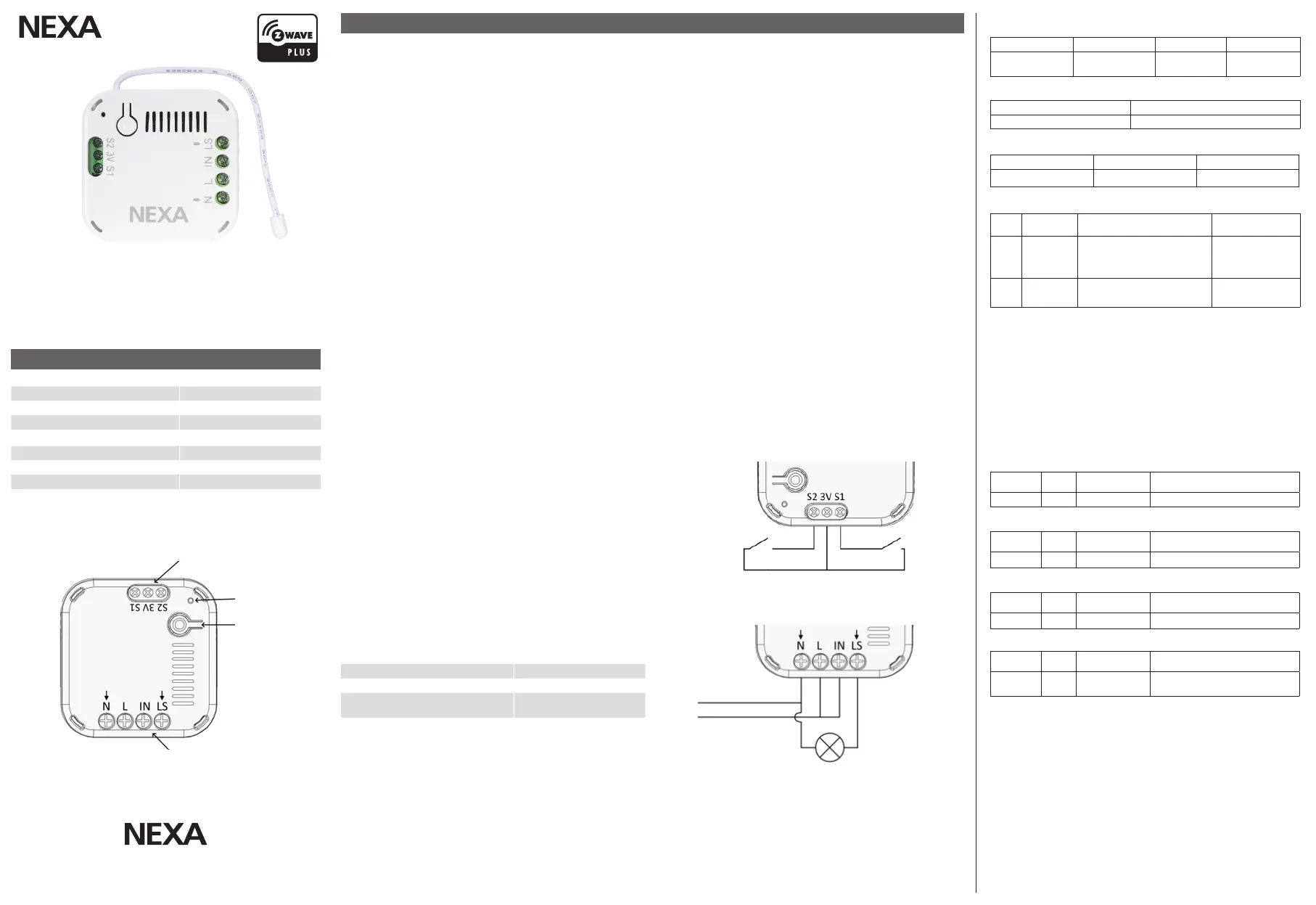
| Model: | AN-179 |
| Bredde: | 43 mm |
| Dybde: | 16 mm |
| Højde: | 42 mm |
| Produktfarve: | Hvid |
| Driftstemperatur (T-T): | -10 - 40 °C |
| Tilsluttet belastning: | 2500 W |
| Forbindelsesteknologi: | Trådløs |
| Indgangsspænding: | 220 - 240 V |
| Driftsfrekvens: | 868.42 MHz |
| Indgangsfrekvens: | 50 Hz |
| Gear rækkevidde: | 0 - 30 m |
Har du brug for hjælp?
Hvis du har brug for hjælp til Nexa AN-179 stil et spørgsmål nedenfor, og andre brugere vil svare dig
Modtager Nexa Manualer

20 August 2024

20 August 2024

19 August 2024

17 August 2024
Modtager Manualer
- Music Hall
- Antelope
- Jensen
- Classé
- ART
- Neve
- Konig & Meyer
- Fishman
- Ibiza Sound
- Velleman
- Megasat
- iRV Technologies
- Lotronic
- Vocopro
- Kali Audio
Nyeste Modtager Manualer

15 December 2025

11 December 2025

8 December 2025

8 December 2025

7 December 2025

7 December 2025

7 December 2025

7 December 2025

6 December 2025

6 December 2025