1
WARNING: Risk of Fire or Electric Shock
• To avoid damage, falling, electric shock or re, do not modify the xture or replace
accessories without conrming with the supplier rst.
• Only authorized, qualied personnel should install this xture and should follow the
owner’s manual. Any improper installation might cause failure, electric shock, re
or other injury, damage or hazard.
• Disconnect power before installation or any maintenance of the xture.
• To prevent re, these xtures are rated for use in 120V (62-1860 & 62-1861: 120-277V).
• The product is for interior use only, suitable for damp location.
• Protect the product against direct contact with water.
• For use in environments where an accumulation of non-conductive dust on the
xture may be expected.
• Clean with a soft or damp cloth, making sure the power is OFF.
• The product (without integrated sensor) is dimmable and compatible with most
residential dimmers.
• 5 Year limited warranty only in respect of any defect in material.
IMPORTANT: This product must be installed in accordance with the applicable
installation code by a licensed electrician familiar with the construction and operation
of the product and the hazards involved.
LED CLOUD FIXTURES
Models: 62-1850, 62-1851, 62-1852, 62-1853,
62-1858, 62-1859, 62-1860, 62-1861
Satco Products, Inc.
Brentwood, NY 11717
INSTALLATION AND SAFETY INSTRUCTIONS
IMPORTANT: Read before installing xture. Retain for future reference.
© Copyright 2024 Satco Products, Inc. 7/24 v1.0
11.5W: 62-1850, 62-1851 (w/Sensor)
14W: 62-1860 (120/277V 0-10V, Dimmable)
O/ 11" (279mm) x 3.13"D (79mm)
14W: 62-1852, 62-1853 (w/Sensor)
17W: 62-1861 (120/277V 0-10V, Dimmable)
O/ 14" (355.5mm) x 3.17"D (80mm)
25W: 62-1858, 62-1859 (w/Sensor)
O/ 19" (482.6mm) x 4.13"D (105mm)
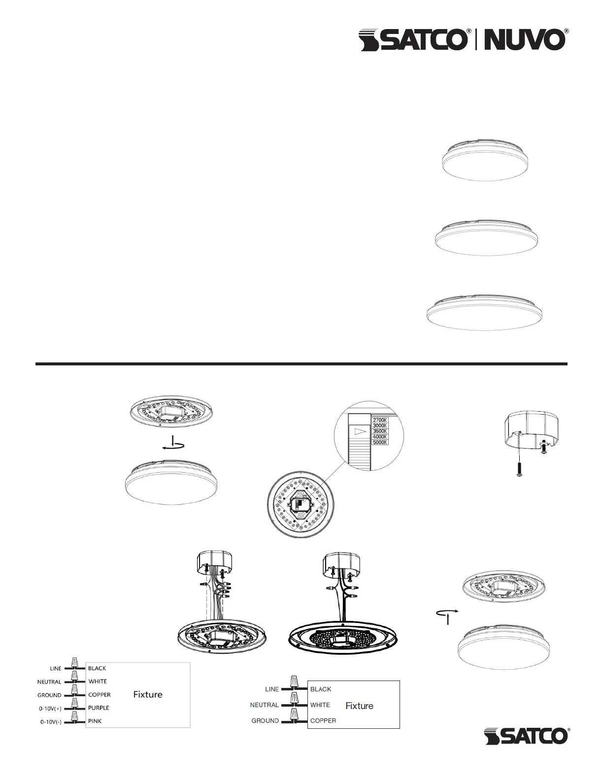
INSTALLATION:
STEP 1: Turn OFF
power supply before
installation. Remove
the diffuser (shade).
STEP 2: Select
your preferred color
temperature (CCT) by
moving the switch to
either 2700K, 3000K,
3500K, 4000K or
5000K.
STEP 5: Replace the diffuser
(shade). Installation is complete.
Turn power ON.
STEP 3: Screw
the (2) screws to
3" or 4" junction
box using the
keyhole slots on
the pan of the
xture.
Wiring Diagram
Wiring Diagram
Only for 62-1860 & 62-1861
0-10V dimmable models.
STEP 4: Connect wires
separately (see wiring diagrams).
Cap all connections with wire
nuts (included). Push xture and
twist clockwise to lock the xture
with screws. Tighten the screws
with a screwdriver.


