539465
GB
FR
DE
Register online: silverlinetools.com
3
GUARANTEE
YEAR
ANS DE GARANTIE
JAHRE GARANTIE
AÑOS DE GARANTÍA
ANNI DI GARANZIA
JAAR GARANTIE
LATA GWARANCJI
silverlinetools com
FR Testeur LAN
DE Netzwerktester
ES Comprobador de cable LAN
IT Tester LAN
NL LAN Tester
PL Tester kabli
LAN Tester RJ11, RJ12 & RJ45
Version date: 04.01.2019
234
5
8
1
9
6
7
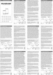
1. Master Unit
2. RJ11/RJ12: 6P6C - 6P4C Input - Master Unit
3. RJ45: 8P8C – 8P4C Input - Master Unit
4. RJ45: 8P8C – 8P4C - Remote Unit
5. Remote Unit
6. RJ11/RJ12: 6P6C - 6P4C Input - Remote Unit
7. ON/OFF Switch
8. Power Indicator Light
9. LED Connection Indicators
Operation
Testing a cable
IMPORTANT: Please note the ‘G’ connection will only indicate if testing cables with a grounded
connection (connector plugs with a conductive surface and cable with braided or foil-wrapped sleeve
to the inner cables).
1. Insert one end of the cable in the appropriate socket on the Master Unit (1), the other end into the
appropriate socket on Remote Unit (5)
2. Slide the Switch (7) to ON (or Slow)ON/OFF
3. LED Connection Indicators (9) should illuminate in accordance with guidance below
4. If no lights illuminate, check that the cables are connected properly and check the battery
No fault
• RJ45 cables: The LED Connection Indicators (9) on the Master Unit (1) and Remote Unit (5)
will illuminate sequentially from 1 to G
• RJ11 & RJ12 cables: 1 to G on the Master Unit; 1-2-3-4-5-6 (RJ12), 2-3-4-5 (RJ11) on the Remote Unit
Open circuit
(Wire not connected to terminal)
• If one wire, for example No. 3, has an open circuit, the No. 3 light on the Master Unit (1) and Remote Unit
(5) will not illuminate
• If several wires have an open circuit, the respective lights will not illuminate
• If less than two wires are connected, no lights will illuminate
Short circuit
(Wire connected to wrong terminal)
• If one pair is connected incorrectly, for example No. 2 and No. 4, then the following lights
will illuminate:
Master Unit (1): 1-2-3-4-5-6-7-8-G
Remote Unit (5): 1-4-3-2-5-6-7-8-G
• If two or more wires are short circuited, the LEDs on the Master Unit (1) will illuminate
normally and sequentially
As part of our ongoing product development, specications of Silverline products may alter without notice.
Intended Use
This LAN Tester has 8P8C and 6P6C sockets for testing RJ11, RJ12 and RJ45 cables and network socket
connections. The tester can indicate incorrect connections, short circuits and open circuits.
Before Use
Connecting the battery
This product requires a 9V battery (not supplied)
1. Slide the cover panel from the back of the Master Unit (1) to open the battery compartment
2. Connect the battery - align the battery with the connector so that the terminals on the battery and the
connector snap-t together securely.
3. Insert the battery into the compartment, and slide the panel back into place
Operating speeds
• The unit has two operating speeds, selected via the Switch (7):ON/OFF
• ON - Standard speed, Power Indicator Light (8) ashes rapidly
• Slow - Slow speed, Power Indicator Light (8) ashes slowly and the test results are displayed
in a slower progression for easier reading
• On the Remote Unit (5), any LED corresponding to one of the shorted wires will illuminate less brightly
or will not be illuminated at all
Testing a network
IMPORTANT: ‘G’ will only indicate if the cables used have a ground/earth connection and the network
sockets have a ground/earth connection.
To test the connection between socket at location A which is directly wired to socket at location B
1. Disconnect any cables from additional sockets connected in the network
2. Slide the Remote Unit (5) off the Master Unit (1) so that the two units are separate
3. Connect cable from Master Unit (1) to network socket at Location A
4. Connect cable from Remote Unit (5) to network socket at location B
Operation as per ‘Testing a cable’ above.
Note: Check integrity of cables that you use to connect to the network before you test the network.
Maintenance
• Do not attempt to repair this product. It contains no serviceable parts
• Keep the sockets on this product clear of dust
• Store this product in the pouch provided, together with the instruction leaet
• If the product will not be used for an extended period of time, it is recommended
that you remove the battery
Disposal
Always adhere to national regulations when disposing of electrical and electronic equipment (WEEE)
that is no longer functional and are not viable for repair.
• Do not dispose of waste electrical and electronic equipment (WEEE), with household waste
• Contact your local waste disposal authority for information on the correct way to dispose of electrical
and electronic equipment (WEEE)
Specication
Battery:...................................1 x 9V (PP3)
LED Indicators:...................................2 x 9
Connectors:.............................................
2 x RJ11/RJ12: 6P6C - 6P4C Input
2 x RJ45: 8P8C – 8P4C Input
Size (H x W x L):..........108 x 96 x 28mm
Weight:.............................................110g
1. Unité principale
2. RJ11/RJ12 : 6P6C - Borne 6P4C - Unité principale
3. RJ45 : 8P8C - Borne 8P4C - Unité principale
4. RJ45 : 8P8C - Borne 8P4C - Unité à distance
5. Unité à distance
6. RJ11/RJ12 : 6P6C - Borne 6P4C - Unité à distance
7. Interrupteur marche/arrêt
8. Témoin lumineux de mise sous tension
9. Indicateurs de connexion LED
Consignes D’utilisation
Tester un câble
IMPORTANT : Veuillez noter que la connexion « G » ne sera indiquée que si vous testez des câbles dotés
d’une connexion avec mise à la terre (connecteurs ayant une surface conductrice et un câble avec gaine
tressée ou à feuille d’aluminium).
1. Introduisez une extrémité du câble dans la borne adaptée de l’unité principale (1),
et l’autre extrémité dans la borne adaptée de l’unité à distance (5).
2. Faites coulisser l’interrupteur marche/arrêt (7) sur la position ON (ou Slow*).
3. Les Indicateurs de connexion LED (9) s’allument conformément aux indications données ci-dessous.
4. Si aucun voyant ne s’allume, vériez que les câbles soient correctement raccordés et vériez
l’état de la pile.
Aucun défaut
• Câbles RJ45 : les Indicateurs de connexion LED (9) de l’unité principale (1) et de l’unité à distance (5)
s’allumeront l’un après l’autre de #1 à G.
• Câbles RJ11 et RJ12 : les voyants de l’unité principale s’allumeront l’un après l’autre de #1 à G ; Les
voyants # 1 – 2 – 3 – 4 – 5 – 6 (RJ12) et 2 – 3 – 4 – 5 (RJ11) s’allumeront sur l’unité à distance.
Circuit ouvert
(Fil non connecté à la borne)
• Si l’un des ls, #3 par exemple, est sur circuit ouvert, le voyant #3 de l’unité principale et celui
de l’unité à distance resteront éteints.
• Si plusieurs ls sont sur circuit ouvert, les voyants respectifs resteront éteints.
• Si moins de deux ls sont connectés, aucun voyant ne s’allumera.
Court-circuit
(Fil connecté à la mauvaise borne)
• Si une paire de ls n’est pas connectée correctement, #2 et #4 par exemple, les voyant s’allumeront de
la manière suivante :
Unité principale (1) : # 1 – 2 – 3 – 4 – 5 – 6 – 7 – 8 - G
Unité à distance (5) : # 1 – 4 – 3 – 2 – 5 – 6 – 7 – 8 - G
• Si deux ls ou plus sont court-circuités, les voyants de l’unité principale (1) s’allumeront
normalement et successivement.
Du fait de l’évolution constante de notre développement produit, les caractéristiques des produits
Silverline peuvent changer sans notication préalable.
Usage Conforme
Ce testeur LAN possède des prises 8P8C et 6P6C pour tester les câbles RJ11, RJ12 et RJ45 ainsi que les
points de connexion réseau. Ce testeur peut indiquer les connections incorrectes, les courts-circuits et les
circuits ouverts.
Avant l’utilisation
Installation de la pile
Ce produit fonctionne avec une pile de 9 V (non fournie).
1. Pour ouvrir le compartiment à piles, faites coulisser le couvercle situé sur l’arrière de l’unité principale (1).
2. Alignez la pile avec le connecteur de manière à ce que les bornes de celle-ci et le connecteur
s’emboîtent en toute sécurité.
3. Insérez la pile dans le compartiment puis réinstallez le couvercle.
Vitesses de fonctionnement
• L’appareil est doté de deux vitesses de fonctionnement, pouvant être sélectionnées à l’aide
de l’interrupteur marche/arrêt (7) :
• ON – Vitesse standard, le voyant lumineux (8) clignote rapidement.
• *Slow – Vitesse lente, le voyant lumineux (8) clignote lentement et les résultats du test s’afchent plus
lentement pour faciliter le relevé.
• Sur l’unité à distance (5), les voyants correspondants aux ls court-circuités s’allumeront faiblement ou
ne s’allumeront pas.
Tester un réseau
IMPORTANT : ‘G’ ne sera indiqué que si les câbles et prises réseaux utilisés sont dotés d’une connexion
mise à la terre (masse).
Pour tester la connexion directe (prise A à B) entre deux prises :
1. Débranchez tout câble présent sur toute autre prise du même réseau.
2. Séparez les deux unités en faisant coulisser l’unité à distance (5) à l’écart de l’unité principale (1).
3. Branchez le câble de l’unité principale (1) sur la prise A du réseau.
4. Branchez le câble de l’unité à distance (5) sur la prise B du réseau.
Suivez ensuite les indications fournies dans la section « Tester un câble » ci-dessus.
Remarque : vériez le bon état des câbles que vous employez pour connecter l’appareil sur le réseau avant
de tester le réseau en question.
Entretien
• Ce produit n’est pas conçu pour être réparé. Il ne contient aucune pièce susceptible d’être remplacée.
• Veillez à ce que les bornes du testeur soient exemptes de poussière.
• Conservez le testeur dans la pochette fournie, accompagné du manuel d’instructions.
• Si l’appareil doit rester inutilisé pendant une période prolongée, il est recommandé de retirer la pile.
Recyclage
Lorsque l’appareil n’est plus en état de fonctionner et qu’il n’est pas réparable, recyclez celui-ci
conformément aux réglementations nationales.
• Ne jetez pas les outils électriques, batteries et autres déchets d’équipements électriques ou
électroniques (DEEE) avec les ordures ménagères.
• Contactez les autorités locales compétentes en matière de gestion des déchets pour vous informer
de la procédure à suivre pour recycler les outils électriques.
Caractéristiques techniques
Pile :...........................................1 x 9 V (PP3)
Indicateurs LED :.....................................2 x 9
Connecteurs :...............................................
2 x RJ11/RJ12 : 6P6C – Borne 6P4C
2 x RJ45 : 8P8C – Borne 8P4C
Dimensions (L x I x H) : ..108 x 96 x 28 mm
Poids :...................................................110 g
1. Sender („MASTER”)
2. RJ11/ RJ12: 6P6C – 6P4C -Buchse am Sender
3. RJ45: 8P8C – 8P4C -Buchse am Sender
4. RJ45: 8P8C – 8P4C -Buchse am Empfänger
5. Abnehmbarer Empfänger („REMOTE“)
6. RJ11/RJ12: 6P6C – 6P4C -Buchse am Empfänger
7. Ein-/Ausschalter
8. Betriebsanzeige
9. LED-Verbindungsanzeiger
• „Slow” – Niedrige Geschwindigkeit: Betriebsanzeige (8) blinkt langsam und die Testergebnisse werden
zur leichteren Ablesbarkeit in langsamerer Abfolge angezeigt.
Betrieb
Kabel prüfen
WICHTIGER HINWEIS: Bitte beachten Sie, dass die „G“-Verbindung nur bei der Überprüfung von
Kabeln mit Schirmanschluss (Anschlussstecker mit leitender Oberäche und Kabel mit geochtener oder
Folienummantelung um den innenliegenden Drähten) angezeigt wird.
1. Stecken Sie ein Kabelende in die entsprechende Buchse am Sender (1) und das andere Ende in die
jeweilige Buchse am Empfänger (5).
2. Stellen Sie den Ein-/Ausschalter (7) auf „ON” (bzw. „Slow”).
3. Die LED-Verbindungsanzeiger (9) leuchten nun gemäß der nachfolgenden Beschreibung auf.
4. Falls keine Leuchtdiode aueuchtet, vergewissern Sie sich, dass die Kabel ordnungsgemäß
angeschlossen sind und überprüfen Sie die Batterie.
Keine störung
• RJ45-Kabel: Die LED-Verbindungsanzeiger (9) an Sender und Empfänger leuchten der Reihe
nach von 1 bis G auf.
• RJ11- und RJ12-Kabel: Der Reihe nach von 1 bis G am Sender und 1-2-3-4-5-6 (RJ12),
2-3-4-5 (RJ11) am Empfänger.
Offener stromkreis
(Ader nicht angeschlossen)
• Wenn ein Kabel, z.B. Ader 3, an einem offenen Stromkreis anliegt, leuchten die LEDs für Ader
3 an Sender und Empfänger nicht auf.
• Wenn mehrere Kabel an einem offenen Stromkreis anliegen, leuchten die entsprechenden
LEDs nicht auf.
• Wenn weniger als zwei Adern angeschlossen sind, leuchten ebenfalls keine LEDs auf.
Kurzschluss
(Ader falsch angeschlossen)
• Bei einem falsch angeschlossenen Kabelpaar, z.B. Ader 2 und Ader 4, leuchten die folgenden LEDs auf:
Sender: 1-2-3-4-5-6-7-8-G
Empfänger: 1-4-3-2-5-6-7-8-G
Aufgrund der fortlaufenden Weiterentwicklung unserer Produkte können sich die technischen Daten von
Silverline-Produkten ohne vorherige Ankündigung ändern.
Bestimmungsgemäße Verwendung
Dieser Netzwerktester ist mit 8P8C- und 6P6C-Buchsen zur Überprüfung von RJ11- , RJ12 und RJ45-
Kabeln und -Netzwerkanschlüssen ausgestattet. Das Gerät kann fehlerhafte Anschlüsse, Kurzschlüsse und
Unterbrechungen anzeigen.
Vor Inbetriebnahme
Anschließen der batterie
Für den Betrieb dieses Gerätes wird eine 9-V-Blockbatterie (nicht im Lieferumfang enthalten) benötigt.
1. Schieben Sie zum Öffnen des Batteriefachs die Abdeckung auf der Rückseite des Senders (1) ab.
2. Schließen Sie die Batterie an, indem Sie die Batteriepole und die Anschlüsse fest verbinden und dabei
auf die Polung achten.
3. Legen Sie die Batterie in das Fach ein und schieben Sie die Abdeckung wieder zurück,
um das Fach zu schließen.
Betriebsgeschwindigkeit
• Das Gerät verfügt über zwei Betriebsgeschwindigkeiten, die sich über den Ein-/Ausschalter
(7) wählen lassen:
• „ON“ – Standardgeschwindigkeit: Betriebsanzeige (8) blinkt schnell.
• Bei zwei oder mehreren kurzgeschlossenen Kabeln, leuchten die LEDs am Sender (1)
normal und nacheinander.
• Bei kurzgeschlossenen Kabeln, leuchten die jeweilig entsprechenden LEDs auf dem Empfänger (5),
weniger hell oder überhaupt nicht.
Netzwerk prüfen
WICHTIGER HINWEIS: „G” wird nur angezeigt, wenn die verwendeten Kabel und die Netzwerkbuchsen
über eine Masseverbindung verfügen.
Überprüfung der Verbindung zweier direkt miteinander verbundener Buchsen an Position A und Position B:
1. Nehmen Sie alle Kabel von zusätzlich ans Netzwerk angeschlossenen Buchsen.
2. Schieben Sie den Empfänger (5) vom Sender (1) herunter, so dass die beiden Einheiten
voneinander getrennt sind.
3. Schließen Sie das Kabel des Senders (1) an Position A an die Netzwerkbuchse an.
4. Schließen Sie das Kabel des Empfängers (5) an Position B an die Netzwerkbuchse an.
Der Betrieb erfolgt gemäß „Kabel prüfen“ oben.
Hinweis: Prüfen Sie vor der Überprüfung des Netzwerks die zum Anschluss an das Netzwerk verwendeten
Kabel auf Beschädigungen.
Wartung
• Führen Sie keine Wartungsversuche an diesem Gerät durch. Es enthält keine wartbaren Teile.
• Halten Sie die Gerätebuchsen stets frei von Staub.
• Bewahren Sie dieses Gerät zusammen mit der Bedienungsanleitung in der mitgelieferten Hülle auf.
• Nehmen Sie bei Nichtgebrauch über einen längeren Zeitraum die Batterie aus dem Gerät.
Entsorgung
Beachten Sie bei der Entsorgung von defekten und nicht mehr reparablen Elektro- und Elektronikgeräten
die geltenden Vorschriften und Gesetze.
• Elektrische und elektronische Altgeräte nicht über den Hausmüll entsorgen.
• Lassen Sie sich von der zuständigen Behörde bezüglich der ordnungsgemäßen
Entsorgung von Elektro- und Elektronikgeräten beraten.
Technische daten
Batterie:.........1 Stck. 9-V-Blockbatterie (PP3)
LED-Anzeigen:................................2 x 9 Stck.
Anschlüsse:....................................................
2 x RJ11/RJ12: 6P6C – 6P4C -Buchse
2 x RJ45: 8P8C – 8P4C -Buchse
Abmessungen
(H x B x T):108 x 196 x 28 mm
Gewicht:................................................110 g