Tripp Lite HCINT150SL Manual


Læs gratis den danske manual til Tripp Lite HCINT150SL (12 sider) i kategorien Batterioplader. Denne vejledning er vurderet som hjælpsom af 3 personer og har en gennemsnitlig bedømmelse på 3.6 stjerner ud af 2 anmeldelser. Har du et spørgsmål om Tripp Lite HCINT150SL, eller vil du spørge andre brugere om produktet?

Side 1/12
23-08-313-933217 REV D
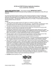
HC150 and HCINT150 Series Application Guidelines
Series AGSM7328, AGSM7892
SAVE THESE INSTRUCTIONS – This manual contains IMPORTANT SAFETY
INSTRUCTIONS that should be followed during installation and maintenance of the UPS and
batteries.
The HC15
0 and HCINT150 series of hospital cart power modules are designed to provide AC voltage output
power from either utility provided AC input voltage or from inverting DC power from a battery. The HC150SL,
lead acid (SLA) battery. The HCINT150L model works only with a Li-Ion battery. To ensure proper operation, the
following guidelines should be observed:
General:
1.
The power module can support continuous AC loads up to a maximum of 150VA or 150
W.
2.
The HC150SL and HC150LVR models require 60Hz utility input. The HCINT150SL and
HCINT150L models
automatically
select the last utility frequency encountered (50Hz or 60Hz) for invert mode operation.
3.
The appliance inlet dongle serves as a disconnect device and shall be easily accessible
.
4.
Alternately, the socket-outlet of the end-product shall be installed near the equipment and shall be easil
y
acce
ssible or disconnect device provided within the end produc
t.
5.
A Remote User Interface (RUI) module must be connected to the power module using two CAT-5 cables
.
The COMM1
jacks should be connected together and the COMM2 jacks should be connected
together. If the
cabl
es are not connected or if they are interchanged, the power module will not operate. The
RUI may be
either a T
ripp Lite RUI or a customer designed RUI that meets Tripp Lite specifications.
6.
The power module is able to provide many operational parameters to monitoring software (such as Tri
pp
Lite’s PowerA
lert) running on a computer that has a USB connection to the power modul
e.
7.
The rated temperature range for the fan inlet air to the power module is 0°C to 40°C.
8.
The power module has internal over temperature protection. If the internal temperature becomes grea
ter than
85°C, the power m
odule will shut down (no VAC output and no charging). If the
temperature drops below
85°C, charging will resume but the VAC output will remain off until the On switch on the RUI is pressed.
9.
Whe
n using a Li-Ion battery, a communication cable is required from the power module COMM3 connec
tor to
the battery
communication connector. This allows the battery to communicate its operating parameters
to the
power modul
e, including state of charge and over temperature conditions (the power module
will interrupt
current into or out of a battery if a battery reports an internal temperature alarm exceeding about 60°C).
Cautio
n: To prevent possible damage to the power module, make battery DC power connections be
fore
makin
g communication connections (and reverse the procedure when disconnecting the ba
ttery).
10.
When using SLA batteries with HC150SL, HC150LVR, or HCINT150SL models, a communication cable is
not
use
d. To provide added fault protection for SLA batteries, the HC150SL and HCINT150SL models may be
equipped with optional temperature sensors (Tripp Lite P/N AC8441) connected from their THERM1 and
/or
THERM
2 connectors to the negative terminals of the batteries. The sensors need to be enabl
ed by
rep
rogramming the power module using a software tool available from Tripp Lite. The sensor
s allow the
power module to interrupt current into or out of a battery if a battery temperature exceeds 50°C. If a sensor
has been enabled, a missing or open sensor
will also cause a shut down.
11. C
AUTION: Double Pole/Neutral Fusing
.
1000 Eaton Boul
evard
Cleveland, OH 44122
United States
TrippLite.Eaton.com
Tripp Lite is now part of Eaton.
23-08-313-933217 REV D
Battery:
1. The power modules are designed to work with a 12.8V
DC
Li-Ion battery rated at 24AH to 40AH. The
HC150SL, HC150LVR, and HCINT150SL models are also capable of operating with a 12.0V
DC
SLA battery
rated at 33AH to 66AH. Smaller SLA batteries may be paralleled to provide the rated AH capacity. Consult
with Tripp Lite to confirm that the intended battery is characterized for use with the power module.
2. The HC150SL, HCINT150L, and HCINT150SL models are shipped programmed for use with a Li-Ion battery.
They are able to detect which compatible Li-Ion battery is attached by communicating with the battery through
the battery communication cable. To change to SLA battery type, a HC150SL or HCINT150SL must be re-
programmed using a software tool available from Tripp Lite.
3. The HC150LVR model is shipped programmed for use with a 33AH SLA battery (9.9A charging current). To
change to Li-Ion battery type, it must be re-programmed using a software tool available from Tripp Lite.
4. The power module charger will charge a 40AH Li-Ion battery with a 20A maximum current or a 24AH Li-Ion
battery with a 12A maximum current. The power module will provide an appropriate charging current (9.9A to
20A) for 33AH to 66AH SLA batteries when programmed with the software tool available from Tripp Lite. If
the internal temperature of the power module reaches 65°C while charging at 20A, it will fold back the
charging current to 16A to prevent overheating (charging at 16A or less reduces internal temperatures).
5. A Li-Ion battery provides its % capacity level to the power module through the battery communication cable.
The power module will calculate the % capacity of a SLA battery by measuring battery voltage and current.
6. The power module includes a low voltage cutoff (LVC) function that will remove any load on the battery when
the battery is depleted to zero % capacity (Li-Ion) or 10.5V (SLA). If any other DC loads are present in the
system, it is recommended that they include their own LVC function in order to prevent excessive battery
depletion and to facilitate quick recharging of the battery.
7. Following the initial battery installation or a battery replacement, the power module should be allowed to
charge the battery to full capacity before starting a discharge cycle of the battery. When a Li-Ion battery is
first connected to a power module, there may be a delay of up to 60 seconds before full charging current is
delivered to the battery.
8. If a Li-Ion battery has a voltage less than 10.8V – 11.4V (depending on manufacturer), then the charger will
start in recovery mode with a 1A charging current. If the battery voltage recovers above the threshold in less
than 45 minutes, then full charging current will be resumed. be considered defective If not, the battery will
and the power module will shut down. There is no VAC output voltage while in battery recovery mode.
9. A SLA battery will be charged normally as long as its voltage is greater than 9.6V. If the battery voltage is
less than 9.6V, it will be considered defective and the power module will shut down.
Installation:
1. Adequate provision for airflow needs to be provided at both the inlet and exhaust vents of the power module.
A minimum of 6 square inches of open area cross section should be provided from room ambient air to the
power module inlet. A minimum of 6 square inches of open area cross section should also be provided from
the power module exhaust to room ambient air. There should be no air obstructions within 0.5 inches of the
fan and vented ends of the power module.
2. A baffle or air deflector is recommended at the fan end so that the air intake is raised at least 6 inches above
floor level to prevent dust accumulation in the power module.
3. The power module may be mounted in any orientation. Threaded 8-32 inserts are provided on three surfaces
to facilitate mounting.
4. The AC voltage input and output connections are made with user supplied cables to the IEC C14 input
connector and IEC C13 output connector on the power module. Use only with approved plug/cord sets
according to the equipment electrical ratings, cord length for HCINT150 AC output shall not exceed 10
meters. No external fusing is needed since safe operation is assured by internal non-replaceable fuses.
However, if a customer wishes to prevent the internal fuses from blowing in the event of an extreme overload,
then an external fuse or circuit breaker rated at 6A should be provided on the AC voltage input.
5. A user supplied battery DC cable is needed to connect the battery to the power module DC input connector
(Anderson Power Products type SB 50). Proper polarity must be observed. The voltage drop in the cable
must be less than 0.1V. The cable should have a minimum wire size of 12AWG and a maximum length of 30
inches. Larger wire size and shorter length improves performance.


Produkt Specifikationer

Mærke: Tripp Lite
Kategori: Batterioplader
Model: HCINT150SL
Bredde: 292.1 mm
Dybde: 152.4 mm
Højde: 88.9 mm
Vægt: 6210 g
Antal pr. pakke: 1 stk
Produktfarve: Grå
Pakkevægt: 6850 g
Pakkedybde: 218.4 mm
Pakkebredde: 360.7 mm
Pakkehøjde: 177.8 mm
Husmateriale: Stål
Strømforsyningstype: Indendørs
Kabler inkluderet: USB
Udgangseffekt: 150 W
LED-indikatorer: Power, Status
Udgangsspænding: 230 V
Kabellængde: 0.15 m
Harmoniseret systemkode (HS): 85044095
Bæredygtighedscertifikater: RoHS
Indgangsspænding: 230 V
Hovedkassen højde (udvendigt): 177.8 mm
Hovedkassens længde (udvendigt): 218.4 mm
Hovedkassens bruttovægt (udvendigt): 6849 g
Hovedkassens bredde (udvendigt): 360.7 mm
Oprindelsesland: Kina
Indgangsstrøm: 15 A
Stik: C13; C14
Produkter pr. hovedkasse (udvendigt): 1 stk
Indgangsfrekvens: 50 Hz
DC udgangsspænding: +12V
Output strømkapacitet (VA): 0.150 kVA
Uddgående frekvens: 50 Hz

Har du brug for hjælp?

Hvis du har brug for hjælp til Tripp Lite HCINT150SL stil et spørgsmål nedenfor, og andre brugere vil svare dig


Batterioplader Tripp Lite Manualer
Batterioplader Manualer

Nyeste Batterioplader Manualer