1
IN2004 Series • Setup Guide
IMPORTANT NOTE:
Go to www.extron.com for the complete IN2004 Series user guide, installation instructions, and specications
before connecting the product to the power source.
The Extron IN2004 Series are compact, four-input scaling switchers that support video resolutions up to 4K @ 60 Hz at 4:4:4 color
sampling. Integrating HDMI and audio sources into presentation systems, they incorporate Extron-patented Vector™ 4K scaling
technology specically engineered for critical video processing applications. The IN2004 Series deliver automatic switching and
provide advanced features such as seamless transition eects, logo keying, congurable input loop-through, audio embedding and
de-embedding, mixing, and ducking. With these capabilities and more, the IN2004 Series are ideal for board rooms, collaboration
spaces, and other professional AV venues. For lecture halls and larger installations spanning long distances, the DTP3 IN2004 DO
and DI/DO models with DTP3 extension of AV and control signals are also available.
The IN2004 Series scalers provide audio signal processing and control by allowing adjustment of the input audio format, audio gain
and attenuation, mixing, ducking, audio muting, analog output format, and output volume. The stereo and dual independent mono
balanced and unbalanced analog audio line input can be mixed with program audio or audio le playback. The IN2004 Series
scalers have two audio output paths: Digital Out 1A/1B and an analog 5-pole captive screw output on the rear panel. These two
output groups each have unique DSP functions for mixing, ltering, and dynamics. Each individual output connector supports
discrete audio mute control. Audio settings are made via Extron Simple Instruction Set™ (SIS) and Product Conguration Software
(PCS) (see the IN2004 Series User Guide and the IN2004 Series Help File for more information).
NOTE: For full installation, conguration, and operation details, see the IN2004 Series User Guide at www.extron.com. For
information on conguration using PCS, see the IN2004 Series Help File within the software.
Installation
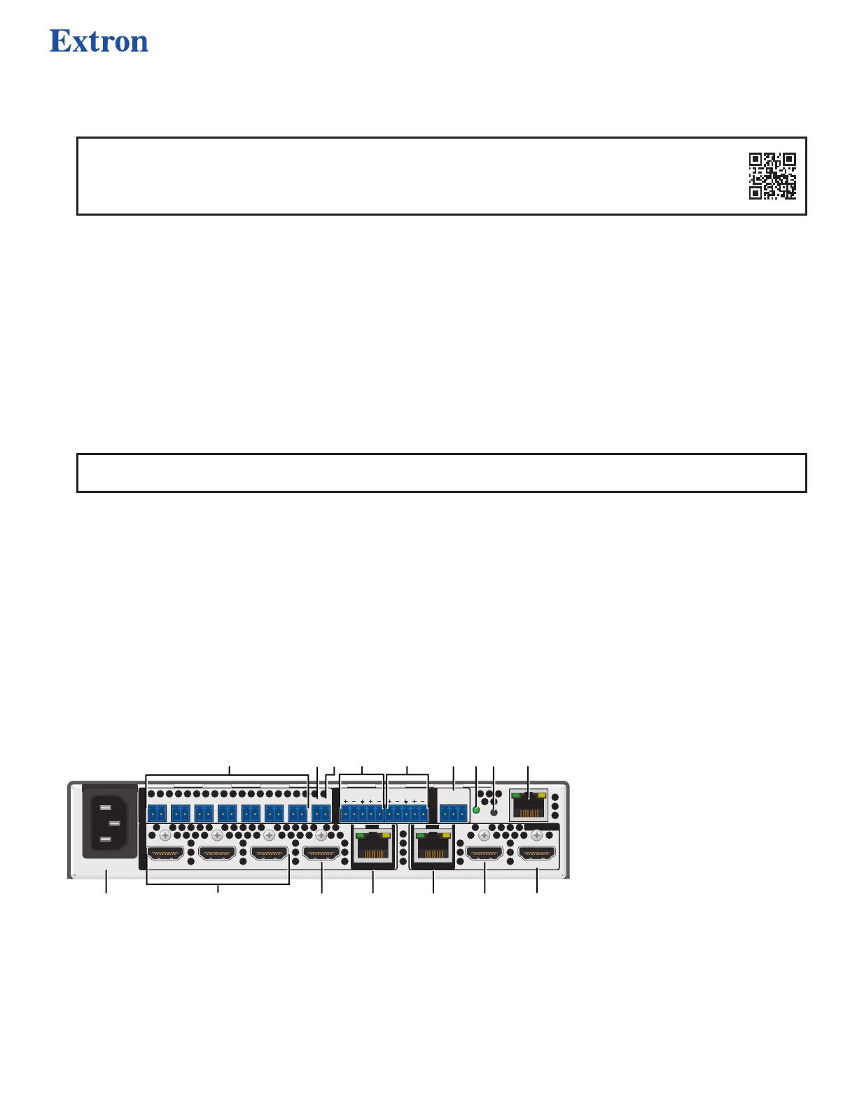
Rear Panel Features
The IN2004 Series models have dierent rear panel inputs and outputs as described below. Figure 1 shows the
DTP3 IN2004 DI/DO model as an example, because it contains all connector types available on the IN2004 Series.
• IN2004 standard — Inputs: Four HDMI. Outputs: Two HDMI.
• DTP3 IN2004 DO — Inputs: Four HDMI. Outputs: Two HDMI and one RJ-45
twisted pair for DTP, DTP3, XTP, and HDBT output (mirrors the output of the scaler).
• DTP3 IN2004 DI/DO — Inputs: Four HDMI and one RJ-45 twisted pair for DTP,
DTP3, or XTP input (congurable to use in place of HDMI input 4)
Outputs: Two HDMI and one RJ-45 twisted pair for DTP, DTP3, XTP, and HDBT
output (mirrors the output of the scaler).
100-240V
~
1.4A MAX
50-60Hz
INPUTS
CONTACT
AUDIO
REMOTE
OUTPUTS
1 2 3 4
4
1A 1B
CONFIGURABLE
1C
CT1 GV+CT2 CT3 CT5 CT6 CT7CT4
1IN2 1OUT 2
IN
SIGLINK
OUT
SIGLINK
RS-232
Tx Rx G
LAN
RESET
A
C
D
E
H
J
I
L
P
K
M
N
O
F
G
Figure 1. Rear Panel Connectors — DTP3 IN2004 DI/DO
Mounting and Cabling
Step 1 — Mount the device
a. Turn o or disconnect all equipment power.
b. Place the scaler on top of a flat surface using the provided rubber feet, mount it under a table using an optional kit for under
desk mounting, or attach it to a rack shelf using an optional rack shelf-mounting kit (kits are available at www.extron.com).
A
AC power connector
B
HDMI INPUTS
C
HDMI input 4
D
TP RJ-45 input 4
E
TP RJ-45 output 1C
F
HDMI output 1A
G
CONFIGURABLE HDMI output 1B
H
LAN connector
I
RESET button
J
RESET LED
K
REMOTE RS-232 connector
L
Analog AUDIO output
M
Analog AUDIO input
N
+V port (for tally voltage output)
O
Ground pin (for contact ports)
P
Contact/tally connectors
1