6LE009010A
Motion detector Highbay DALI-2
Rilevatore di movimento Highbay
Electrical equipment may only be installed and
assembled by a qualified electrician in accor-
dance with the relevant installation standards,
regulations, directives and safety and accident
prevention directives of the country.
Failure to comply with these installation inst-
ructions may result in damage to the device,
Due to its detection behaviour the device is not
suitable for use in burglary detection or alarm
These instructions are an integral component
of the product and must be retained by the end
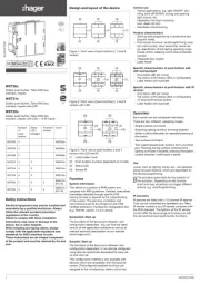
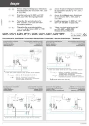
Design and layout of the device
(2) Mounting device locking screw
(5) Detector lens with integrated status LED red/
(6) Response brightness potentiometer
(7) Potentiometer delay time
(8) Cover for potentiometer
- Automatic switching and control of DALI-2
- Surface-mounted installation
- Detection of motion especially for areas with
- Response brightness and daylight control can
- Operating mode: automatic/semiautomatic can
be set via IR configuration hand-held transmitter
- Only suitable for DALI-2 broadcast
- Older DALI devices can be controlled without
Behaviour during operation
The motion detector detects heat motion caused
by people, animals, or objects in accordance with
- will be switched on for the delay time if move-
ments are detected in the detection area and
the set response brightness is undershot. Each
detected movement restarts the delay time.
- will be switched off if no additional movements
are detected in the detection area and the set
delay time has elapsed or the set response
Information for electricians
Installation and electrical connection
Touching live parts can result in an
An electric shock can be lethal!
Disconnect the connecting cables
before working on the device and cover
all live parts in the area!
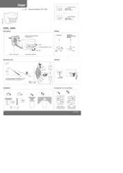
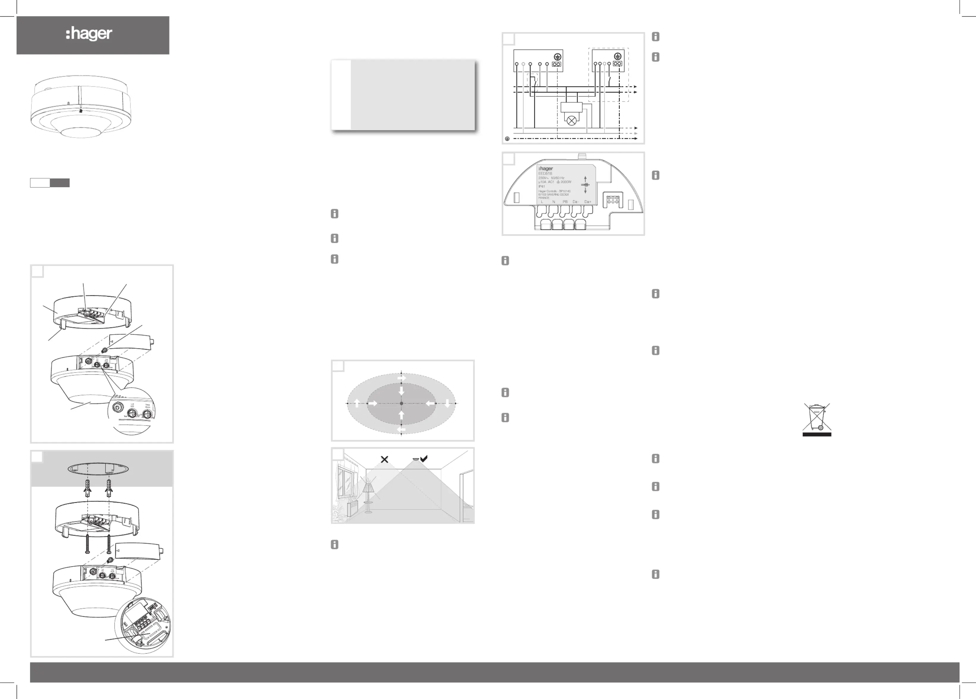
Selecting installation location
The motion detector must be installed horizontally
on the ceiling. It has a detection area of a maxi-
mum of approx. 22 x 12 m. The diameter of the
detection area depends on the installation height.
At an installation height of 8 m, the diameter at
ground level is approx. 22 x 12 m. The diameter of
the inner detection area with enhanced detection
sensitivity is 14 x 8 m (Figure 2).
At an installation height greater than 8 m, the
detection area increases. At the same time, the
detection sensitivity decreases.
The device must be completely installed and
closed to meet the degree of protection IP41.
Observe the motion orientation: a distinction is
made between "direct approach" and "transverse
motion". Motions transverse to the motion detec-
tor can be detected better than motions toward
the motion detector (Figure 2).
Avoid sources of interference in the detection
area. Sources of interference, e.g. heating ele-
ments, ventilation systems, air conditioners and
lamps that are cooling down can cause undesi-
red switching (Figure 3).
Select an installation location that is free of
vibration. Vibrations can cause undesired
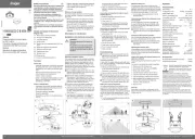
Connecting and installing (Figure 2)
Observe installation direction. Install the device
in such a way that the arrow shown in figure 5
corresponds to the axle of the area to be moni-
Feed the connection cable through the insertion
Install device socket under the ceiling using the
screw dowel set enclosed. If available, install
device socket in a flush-mounted box.
Snap device application module onto base.
Screw in locking screw (9).
The device is in warm-up phase after voltage
recovery. (up to 45s). During this time the status
In test mode, the motion detector works with ma-
ximum response brightness. If motion is detected,
the load is switched for approx. 2 seconds. After
approx. 20 cycles, the operating cycles decrease in
order to protect the connected load.
Set the potentiometer response brightness (6)
to the Test position (Figure 1)
Set potentiometer delay time (7) to minimal (left
The device is in test mode.
Carry out test by moving in the detection area.
If the motion detector switches on without mo-
tion in the detection area, then sources of inter-
ference are present (see Installation location).
After 2 minutes in test mode and no detected
movement, the device is automatically set to
the standard value (500 Lux).
Setting the response brightness
The response brightness is the brightness value
saved in the motion detector; when this value is
undershot the connected load is switched on if
movements are detected. The brightness threshold
can be set continuously between approx. 5 and
2000 Lux (daytime operation/brightness-indepen-
Turn the response brightness potentiometer (6)
The delay time is the period of time set in the
motion detector which is the shortest time that the
lighting is switched on when the response bright-
ness is undershot and motion is detected. The
delay time can be set between pulse /approx. 2 s)
and approx. 5 s to 60 min.
Turn the delay time potentiometer (7) to the
Detecting the DALI-2 status
A detector parameter means that it is possible to
select the dimming status after starting (restoration
of the power supply). After the device is started,
a DALI status is displayed using the green or red
LED. This setting can be activated or deactivated
The green LED flashes whilst a DALI-2 device
The red LED flashes when a DALI-2 bus error
is detected, e.g. no device is connected or a
DALI-2 ballast is detected.
Operating mode: Dimming function active in
After the detection operation, the DALI-2 output re-
gulates the brightness using the specified software
or remote control value. This selection is saved as
standard. The output is activated for the duration
set on the potentiometer (7). If the potentiometer
is set to Adr/On, no light control occurs. The DALI
output is set to the last set value, 100% or another
value that can be changed using the IR remote
control or the push-button.
In the basic setting, the setpoint is 500 lux.
Operating the priority input
A connected push-button is used for forced
switching of the output. The duration of the forced
switching is specified using the time set on the
Set the dimming value by holding down the
Operation with IR configuration hand-held trans-
The IR configuration hand-held transmitter can
be used to change the values set directly on the
device (see Accessories).
A detailed description of the EE807 hand-held
transmitter can be found in the enclosed inst-
Operation by IR hand-held transmitter
The IR hand-held transmitter can be used to trigger
the actions parameterized with the device.
A detailed description of the EE808 hand-held
transmitter can be found in the enclosed inst-
Adjusting the detection area
If the detection area of the detector is too wide or
covers areas that should not be monitored, the
adhesive strips provided can restrict the detection
To extend the detection area, it is possible to
connect additional devices (slave) in parallel to the
master - master/slave operation.
Only relay devices (EER5XX) can be used as
a slave. A further DALI-2 device (EED5XX) is
Additional information on the master-slave
configuration is available on the website on the
download page for the device.
Switches must not be connected to the PB input
of the slave device in slave mode.
Setting the response brightness (6).
Setting the delay time (7).
A detailed description of the EER5XX Salve
device can be found in the corresponding inst-
Set the potentiometer response brightness (6)
to the SL position (Figure 1)
Adjust the potentiometer delay time (7) to suit
the respective application case (additional
information on application cases is available on
the download page for the device).
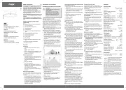
Supply voltage 230 V~, +10%/-15%
Power consumption without load <0.5 W
- Operation 5 s ... 60 min
- Factory setting ~ 15 min
Response brightness, adjustable 5 ... 2000 Lux
- Factory setting 500 Lux
Recommended installation height 6 m ... 9 m
maximum installation height 10 m
Detection area Ø motion (installation height 8 m)
transverse motion towards detector ~ 22 x 12 m
approach detector ~ 14 x 8 m
Detection angle approx. 360°
first and last device max. 50 m
Number of slave devices per master max. 10~
Upstream circuit breaker 10A
Quantity of DALI-2 devices max. 24
Max. DALI-2 bus current 48mA
Relative humidity (no condensation) 30°C, 95%
Operating temperature -5 °C ... +45 °C
Storage/transport temperature -20 °C... +70 °C
Degree of protection IP41
Operating altitude < 2000 m
Dimensions EED518 (Ø x H) 105 x 66.2 mm
- Plug-in terminals (2x) 0.5 ... 2.5 mm²
IR configuration hand-held transmitter EE807
IR hand-held transmitter EE808
Correct Disposal of this product (Waste
Electrical & Electronic Equipment).
(Applicable in the European Union and other
European countries with separate collection
This marking shown on the product or its literature indi-
cates that it should not be disposed with other household
waste at the end of its working life. To prevent possible
harm to the environment or human health from uncon-
trolled waste disposal, please separate this device from
other types of wastes. Recycle the device responsibly to
promote the sustainable reuse of material resources.
Household users should contact either the retailer where
they purchased this product, or their local government of-
fice, for details of where and how they can take this device
for environmentally safe recycling.
Business users should contact their supplier and check
the terms and conditions of the purchase contract. This
product should not be mixed with other commercial was-