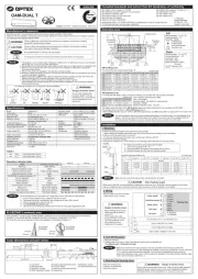
Optex OA-Flex T Manual


Læs gratis den danske manual til Optex OA-Flex T (2 sider) i kategorien Dør / vindue sensor. Denne vejledning er vurderet som hjælpsom af 28 personer og har en gennemsnitlig bedømmelse på 4.9 stjerner ud af 14.5 anmeldelser. Har du et spørgsmål om Optex OA-Flex T, eller vil du spørge andre brugere om produktet?

Side 1/2
(1) Connector
(2) Mounting holes
(3) Operation indicator
(4) Function switch
(5) Dipswitches
(6) Area angle adjustment screws
(7) Area width adjustment screws
(8) Detection window
(9) Area adjustment tool
[mm (inch)]
*1 : BLUEZONE (Lookback), 2nd and 3rd rows have a presence detection function.
*2 :
When using this sensor, the sensor has to be connected to a door system which has the SELV circuit.
*3 : Overcurrent protection with less than 2A.
*4 : See BLUEZONE (Lookback) area
*5 : LED will be turned off approx. 500 ms when the sensor Test output signal works well.
Charts show the values in the following area angle adjustment settings
Test conditions required by EN 16005
Floor : Grey paper
Detection object : EN 16005 CA reference body
Sensitivity : High
Speed of detection object : 50 mm/s
The values above are those of the when tested referring to the test conditions of EN 16005. Detection area
(The emitting area is as shown in above.) Emitting area
Knockout
0.07 (3")
0.06 (2")
0.07 (3")
0.06 (2")
0.14 (6") 0.14 (6") 0.14 (6")
NI-0169-1Original instructions
OA-FLEX T
ENGLISH
5929990 JAN 2021
Manufacturer's statement
Read this operation manual carefully before use to ensure proper operation of this product.
Failure to read this operation manual may cause improper operation and may result in serious injury or death of a person.
The meanings of the symbols are as follows.
1. This product is a non-contact switch intended for header mount or wall mount for use on an automatic
sliding door. Do not use for any other applications.
2. When setting the sensor's detection area, make sure that there is no traffic around the installation site.
3. Before turning the power ON, check the wiring to prevent damage or malfunction of equipment
connected to the product.
4. Only use the product as specified in the operation manual provided.
5. Be sure to install and adjust the sensor in accordance with the local laws and standards of the country
in which the product is installed.
6. Before leaving the installation site make sure that the product is operating properly and instruct the
building owner/operator on proper operation of the door and the product.
7. The product settings can only be changed by an installer or service engineer.
When changed, the changed settings and the date shall be registered in the maintenance logbook
accompanying the door.
It is required to check the operation manual if this symbol is shown on the product.
Failure to follow the instructions that accompany this indication and improper handling
may result in serious injury or death.
WARNING
Failure to follow the instructions that accompany this indication and improper handling
may result in injury and/or damage to property.
CAUTION
Pay special attention to sections with this symbol.
NOTE
NOTE
Do not wash, disassemble,
rebuild or repair the sensor,
otherwise it may cause electric
shock or breakdown of the
equipment.
Danger of electric shock
WARNING
The following conditions are not suitable for sensor installation.
Fog,
Exhaust Wet Vibration Objects Reflection
Specifications
Model
Cover color
Mounting height
Detection area
Detection method
Area angle adjustment
Power supply (*2)
Power consumption
Operation indicator
Output hold time
Response time
Operating temperature
Operating humidity
Noise level
: OA-FLEX T
: Silver/Black
: 2.0 to 3.0 m (6'7" to 9'10")
(2.0m(6'7") to 2.5m (8'2") for
EN16005 compliance)
: See Detection area
: Active infrared reflection (*1)
: Depth : -8° to +8°
Width : ±7°
: 12 to 24 VAC ±10 % (50/60 Hz)
12 to 30 VDC ±10 %
: < 2.0 W (< 5 VA at AC)
: See Operation indicator table
: < 500 ms
: < 300 ms
: -20 to +55°C (-4 to 131°F)
: < 80 %(non-condensing)
: < 70 dBA
Activation output
Safety output
Test input
IP rate
Category
Performance level
ESPE
Weight
Accessories
: Form A relay 50 V 0.3 A Max.
(Resistance load)
: Form A relay 50 V 0.3 A Max.
: Opto coupler
Voltage 5 to 30 VDC
Current 6 mA Max. (30 VDC)
: IP54
: 2 (EN ISO 13849-1:2015)
: d (EN ISO 13849-1:2015)
: Type 2
: 220 g (7.8 oz)
: 1 Operation manual
2 Mounting screws
1 Mounting template
1 Area adjustment tool
1 Cable 3 m (9'10")(*3)
1000 ms 1000 ms
Setting error
Signal saturation
Sensitivity too low(or Sensor failure)
Red & Green blinking
Slow Green blinking
Fast Green blinking
Operation indicator table
Warm-up
Stand-by (Installation mode)
Stand-by (Service mode)
Status
Yellow blinking
Yellow
Operation indicator color
Stand-by (Operation mode)
2nd row detection
BLUEZONE (Lookback) detection (*4)
3rd row detection
4th - 6th row detection
Green
Orange
Red
Red blinking
Blue
Yellow & Green blinking
Communication Test output Turn off 500 ms (*5)
The specifications herein are subject to change without prior notice due to improvements.
NOTE
When dipswitch 15 is set to
"
ON
"
, the BLUEZONE (Lookback) area, that provides extra safety over the threshold is
activated. In case the BLUEZONE (Lookback) function is not required, set dipswitch 15 to
"
OFF
"
.
Do not set the 2nd row overlapping the threshold regardless of the setting of dipswitch 15.
BLUEZONE (Lookback) area
BLUEZONE
(Lookback)
2nd row
3rd row
6th row
5th row
4th row
2nd row overlapping
the threshold
BLUEZONE
(Lookback)
2nd row
3rd row
5th row
4th row
6th row
245(9 5/8") 37(1 7/16")
7.5(5/16")
68(2 11/16")
36(1 7/16") 43(1 11/16")
125(4 15/16")
(1) (2)
(3) (7)(6)(5) (8)
(9)
(4)
Outer dimensions and part names
Complied standards and extract from EC declaration of conformity
For technical document, see European Subsidiary
Notified Body 0044 : TÜV NORD CERT GmbH Langemarckstr. 20 45141 Essen Germany
EN 16005:2012/AC:2015 Chapter 4.6.8 and Annex C
EN 61496-3:2001 clause 4. 3. 5 and 5. 4. 7. 3
EN 61000-6-3:2007 +A1:2011/AC:2012
A. Maekawa
General Manager
OPTEX CO., LTD.
Quality Control Dept.
DIN 18650-1:2010 Chapter 5.7.4 ESPE
Machinery Directive 2006/42/EC
EN 12978:2003 +A1:2009
EMC Directive 2014/30/EU
EN ISO 13849-1:2015
EN ISO 13849-2:2012
EN 61000-6-2:2005/AC:2005
: Emitting spots
: Detection area
: Emitting spots
(can be eliminated)
Detection area
To comply with EN 16005, make sure that the detection area is
within the values of the chart below.
Detection area
The actual detection area may become smaller depending on the ambient light, the color/material of the
object or the floor as well as the entry speed of the object. The sensor may not be activated when the
entering speed of the object or a person is slower than 50 mm/s or faster than 1500 mm/s.
NOTE
BCDEFG
H
I
J
BLUEZONE
(Lookback)
2nd row
3rd row
4th row
5th row
6th row
A
X
Depth
Width
: 8°
: 0°
B
C
D
E
F
G
H
I
J
A
[m(feet,inch)]
2.00 (6'7") 2.30 (7'7") 2.50 (8'2")
0.38 (1'3") 0.46 (1'6") 0.50 (1'8")
2.06 (6'9") 2.48 (8'2") 2.69 (8'10")
1.49 (4 ") 1.80 (5 ") 1.95 (6'5")'11 '11
0.92 (3') 1.11 (3'8") 1.20 (3' ")11
1.75 (5'9") 2.11 (6' ") 2.29 (7'6")11
1.34 (4'5") 1.62 (5'4") 1.76 (5'9")
0.84 (2'9") 1.01 (3'4") 1.09 (3'7")
0.71 (2'4") 0.86 (2'10") 0.94 (3'1")
0.13 (5") 0.16 (6") 0.17 (7")
Emitting area
X
H
J
0.24 (9")
0.85 (2'9")
2.01 (6'7")
0.25 (10")
0.91 (2'12")
2.20 (7'3")
0.23 (9")
0.96 (3'2")
2.44 (8')
A
[m(feet,inch)]
2.00 (6'7") 2.30 (7'7") 2.50 (8'2")
Installation
X
H
Y
Sensor
Door
Header
Floor
a. Place the mounting template at the desired mounting position.
(When setting the detection area close to the door, mount the sensor according to the chart below.)
b. Drill two mounting holes of ø3.4 mm (ø1/8").
c. To pass the cable through the header, drill a wiring hole of ø8 mm (ø5/16").
d. Remove the mounting template.
e. Remove the housing cover. Fix the sensor to the mounting surface with the two mounting screws.
Make sure not to mount the sensor lower than the bottom of header.
1. Mounting
H : Height from the floor to the bottom of the header
(The mounting height is " + ".)H Y
Y : Distance between the bottom of the header and the sensor
X : Distance between the door and the mounting surface
NOTE
CAUTION Risk of getting caught
Make sure to affix the mounting template as described in the above chart, otherwise it can be dangerous since there
may be no detection area around the threshold. Install the sensor as low as possible on the header.
12 to 24 VAC ±10 % / 12 to 30 VDC ±10 %
Form A relay 50 V 0.3 A Max.
Opto coupler / Voltage: 5 to 30 VDC
Form A relay 50 V 0.3 A Max.
Maximum mounting distance ( )Y
X2.00 (6'7")
0
0.05 (2")
0.10 (4") 0.11 (4") 0.11 (4")
0.15 (6") 0.10 (4")
0.20 (8")
0.25 (10")
0.30 (12")
H
0.13 (5")
2.50 (8'2")
0.13 (5")
0.10 (4")
0.09 (4")
[m (feet,inch)]
2.30 (7'7")
0.13 (5")
0.11 (4")
0.10 (4")
0.09 (4")
0.07 (3")
0.06 (2")
0.09 (4")
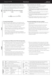
Do not use the sensor without the cover. When using the cable knockout,
install the sensor indoors or use the rain cover (Separately available)
otherwise electric shock or breakdown of the sensor may occur.
WARNING Danger of electric shock
Make sure to connect the cable correctly to the door controller before turning the power ON.
When turning the power ON or after adjusting the settings, do not enter the detection area for more
than 10 s in order to enable the presence detection. Do not touch the dipswitches before turning the
power ON, otherwise an error occurs. After changing the dipswitch settings, make sure to push the
function switch for 2 s.
a. Plug the connector.
b. Supply power to the sensor. Adjust the detection area and set the dipswitches.
(See )Adjustments 3. Dipswitch settings
3. Turn ON the power
NOTE
Place the housing cover. If wiring is to be exposed, break the knockout.
4. Mounting the housing cover
1.White
2.Brown
3.Green
4.Yellow
5.Pink
6.Blue
7.Red
8.Black
9. Grey/Pink
10. Red/Blue
Power supply
Safety output
Activation output 2
1
3
4Test input **
Not used *
Polarity free
2. Wiring
Wire the cable to the door controller.
* The following 2 cables are not used.
Grey/Pink
Red/Blue
** See DIP 8(Test input) comment
in " ".3. Dipswitch settings
Web manual
1
3
4
2
Before starting the procedure, make
sure that the power is turned OFF.
When passing the cable through the
hole, do not tear the shield otherwise
it may cause electric shock or
breakdown of the sensor.
Danger of electric shock
WARNING
The angle of the detection area can both be moved 7° either left or right in 2 steps.
1 2
Left
eliminated
7 8
Right
eliminated
Adjust the detection area width with the adjustment screws.
When adjusting the 2nd row close to the door, see dipswitch 16 in and for the3. Dipswitch settings Reference
easier adjustment.
-8° +8°
DeepShallow
3.5°×23.5°×2
LeftRight
Adjustments
1. Area angle adjustment
a. Area depth angle adjustment
b. Area width angle adjustment
2. Area width adjustment
Select "N.O."/"N.C." for Activation output.
12
N.O. N.C.
12
Activation output
12
When the door remains open and the operation
indicator shows Fast/Slow Green blinking, refer
to . If the door still remainsTroubleshooting
open, set dipswitch 14 to "OFF".
ON
14
OFF*
14
Self monitoring
14
When dipswitch 15 is set to "ON", the
BLUEZONE (Lookback) is active and looks
through the threshold.15
OFF
15
ON
BLUEZONE
(Lookback)
15
11 11
Set dipswitch 11 to "ON" when the sensor
operates by itself (Ghosting). When
dipswitch 11 is set to "ON" the actual
detection area may occur smaller.
OFF ON
Immunity
11
3.0
(9'10")
2.0
(6'7")
1.0
(3'3")
0
[m(feet,inch)] [m(feet,inch)]
2.0
(6'7")
1.0
(3'3")
-1.0
(3'3")
0
ShallowDeep
2.0(6'7")
2.5(8'2")
Make sure that the detection area does not overlap with the door/header, and there is no highly
reflecting object near the detection area otherwise ghosting/signal saturation may occur.
NOTE
When setting the detection area width, make sure to turn the adjustment screws until it clicks.
cannot be eliminated separately, neither can .1 2 7 8
NOTE
Left Right
2.0
(6'7")
1.0
(3'3")
1.0
(3'3")
0 2.0
(6'7")
1.0
(3'3")
1.0
(3'3")
0
[m(feet,inch)] [m(feet,inch)]
2.0(6'7")
2.5(8'2")
[m(feet,inch)]
Front view
2.0(6'7")
2.5(8'2")
2.0
(6'7")
2.0
(6'7")
1.0
(3'3")
1.0
(3'3")
0
1 2 3 4 5 6 7 8
Set the depth rows with dipswitches 9 and 10.
6 rows 5 rows 4 rows 3 rows
109 109 109 109
9
10
Row adjustment
When Dipswitch 13 is set to "ON", both
Activation & Safety output will operate
simultaneously regardless of detection area.
But only Safety output will respond back with
Safety output when it receives Test input.
13
OFF
13
ON
Simultaneous
output
13
* No EN 16005 compliance.
Set dipswitch 16 to "ON" to adjust the 2nd row.
During the installation mode only the 2nd row
remains active and the operation indicator
shows yellow. After setting the row, set
dipswitch 16 to "OFF".
OFF
16
ON
16
Installation mode
16
Service mode
- During "Service mode", 1st row transmitting is OFF and 2nd to 6th row is ON. The operation indicator shows Yellow &
Green blinking.
- After installation, be sure to turn to the "Operation mode" because it does not comply with EN 16005.
- The sensor automatically returns to "Operation mode" after 15 min from the transition.
Keep pushing function switch until the operation indicator goes off.
To Operation mode
Check the operation in the operation mode according to the chart below.
Checking
* : During warm-up, Safety output is constantly active.
Status
Entry
Motion
detection
Entry into
4th to 6th
row
Entry into
3rd row
Entry into
2nd row
Entry into
BLUEZONE
(1st row)
Motion/Presence
detection
Operation indicator
Outside of
detection
area
Stand-by
Green Orange Red Red blinking Blue
Power
OFF
-
None
Activation output
Safety output
ON
OFF
13
ON
OFF
13
N.C.
7
N.O.
N.C.
7
N.O.
12
N.C.
12
N.O.
N.C.
N.O.
1. When turning the power ON, alwayswalk-test the detection area to ensure the proper operation.
2. Do not place any objects that move oremit light in the detection area. (e.g. plant, illumination, etc.)
Inform building owner/operator of the following items
1. Always keep the detection window clean. If dirty, wipe the window with a damp cloth.
Do not use any cleaner/solvent.
2. Do not wash the sensor with water.
3. Do not disassemble, rebuild or repair the sensor yourself, otherwise an electric shock may occur.
4. When the operation indicator blinks green, contact your installer or service engineer.
5. Always contact your installer or service engineer when changing the settings.
6. Do not paint the detection window.
WARNING
NOTE
* After changing the dipswitch settings, make sure to push the function switch for 2 s.
Door opens
when no one
is in the
detection area.
(Ghosting)
Unstable
Waterdrops on the detection window.
The detection area overlaps with that
of another sensor. Check dipswitch 5, 6. (*)Adjustments 3
Objects that move or emit light in the
detection area. Remove the objects.
Sensitivity is too high. Set the sensitivity lower. (*)
Adjust the detection area to "Deep"(Outside).
Or set dipswitch 11 to "ON". (*)
Use the rain-cover. (Separately available)
Or wipe the detection window with a damp cloth.
Do not use any cleaner or solvent.
Or install in a place keeping the waterdrops off.
The detection area overlaps with the
door/header.
Door operation Operation
indicator Possible cause Possible countermeasures
None Wrong power supply voltage. Set to the stated voltage.
Wrong wiring or connection failure. Check the wires and connector.
Door does not
open when a
person enters
the detection
area.
Unstable
Wrong detection area positioning. Check . (*)Adjustments 1, 2, 3
Sensitivity is too low. Set the sensitivity higher. (*)
Short presence timer. Set the presence timer longer. (*)
Dirty detection window. Wipe the detection window with a damp cloth.
Do not use any cleaner or solvent.
Wrong wiring or settings. Check the wires and/or dipswitches.Proper
Troubleshooting
Others Set dipswitch 11 to "ON". (*)
Wrong setting of dipswitches. Check dipswitch 7, 8, 12. (*)Adjustments 3
Proper
Wrong wiring or connection failure. Check the wires and connector.
Fast
Green
blinking
Dirty detection window. Wipe the detection window with a damp cloth.
Do not use any cleaner or solvent.
Sensitivity is too low. Set the sensitivity higher. (*)
Sudden change in the detection area.
Check dipswitch 1 to 4. (*) If theAdjustments 3
problem still persists, hard-reset the sensor.
(Turn the power OFF and ON again)
Proper
Installation mode is set to "ON". Set dipswitch 16 to "OFF". (*)Yellow
Door remains
open Contact your installer or service engineer.Sensitivity too low or sensor failure.
Signal saturation.(2nd and/or 3rd row)
The detection area overlaps with the
door/header. Adjust the detection area to "Deep"(Outside).
Slow
Green
blinking
Remove highly reflecting objects from the
detection area. Or lower the sensitivity. (*)
Or change the area depth angle.
Setting error.
Red &
Green
blinking
After changing the dipswitch settings, make sure to
push the function switch for 2 s.
Remove highly reflecting objects from the
detection area. Or lower the sensitivity. (*)
Or change the area depth angle.
Proper
operation
Signal saturation.
4th, 5th, 6th row and/or BLUEZONE)
Slow
Green
blinking
Service mode is enabled.
Yellow &
Green
blinking
Switch to the Operation mode that keep pushing
function switch until the operation indicator goes
off.
Reference
INFRARED FINDER
Detection area
Detection area
1. Turn the depth angle adjustment screw to the right (Deep) to place the detection area most away from the door.
2. Set INFRARED FINDER sensitivity to "H" (High) and place it on the floor as shown below.
3. Turn the depth angle adjustment screw to the left (Shallow) until the emitting area is placed at the position where
INFRARED FINDER is in the low detection status. (Slow Red blinking)
Area depth adjustment with (Separately available)INFRARED FINDER
*
1
5
6
3
4
7
8
After changing the dipswitch settings, make sure to push the function switch for 2 s.
* Dip switch No. 2 : Not used
3. Dipswitch settings
Safety setting Activation setting Other setting
CommentSettingFunction
Dip
switch
No.
Set the sensitivity according to the mounting
height. Values below dipswitches are
reference only. Adjust the sensitivity
according to your risk assessment.
1
Low
1
High
Sensitivity
When using more than one sensor close to
each other, set the frequency different for
each sensor.
Frequency
Setting4Setting3Setting1 Setting2
65 65 65 65
To enable the presence detection, do not
enter the detection area for 10 s after setting
the timer.
600 s30 s 60 s
43 43 43 43
Presence timer
2 s
(Motion)*
10 ms delay time between Test input and
Safety output.
If the door controller has no Test, put Test
input to "OFF" and do not connect Black and
Red wires.
"High" or "Low" indicates the Test input signal
level from door controller.
N.C.
7
N.O.
7
Safety output
(to door controller)
8 8
OFF
(High)
ON
(Low)
Test input
(from door controller)
Factory default settings
Push 2 s
Dipswitch 8
Test input
OFF
(High)
ON
(Low) 0 V
0 V
Test
Test
EMEA Subsidiary
OPTEX Technologies B.V.
Henricuskade 17, 2497 NB The Hague, The Netherlands
Tel : +31(0)70 419 41 00
info@optex.eu
www.optex.eu
Manufacturer
5-8-12 Ogoto Otsu 520-0101, Japan
Tel : +81(0)77 579 8700
www.optex.net
OPTEX CO., LTD.
Keep pushing function switch for 5 s until the operation indicator starts to blink after off.
To Service mode


Produkt Specifikationer

Mærke: Optex
Kategori: Dør / vindue sensor
Model: OA-Flex T

Har du brug for hjælp?

Hvis du har brug for hjælp til Optex OA-Flex T stil et spørgsmål nedenfor, og andre brugere vil svare dig


Dør / vindue sensor Optex Manualer

Optex

Optex OM-106C Manual

14 November 2024
Optex

Optex OA-6500 Manual

14 November 2024
Optex

Optex OA-Flex T Manual

18 April 2024
Optex

Optex Mirage Manual

16 Februar 2023
Optex

Optex OAM-Dual II Manual

26 Januar 2023

Dør / vindue sensor Manualer

Nyeste Dør / vindue sensor Manualer

Pentatech

Pentatech MA80KM Manual

24 November 2024
Kidde

Kidde K10LLDCO Manual

13 September 2024
Kidde

Kidde 2030-DCR Manual

12 September 2024
Setti+

Setti+ SS524 Manual

19 Juni 2024
Steren

Steren ALA-010 Manual

5 Juni 2024
EZVIZ

EZVIZ T3 Manual

24 Maj 2024
Philips

Philips DES7000RCA Manual

30 Januar 2024