PAC RP5-GM51 Manual
PAC
Ikke kategoriseret
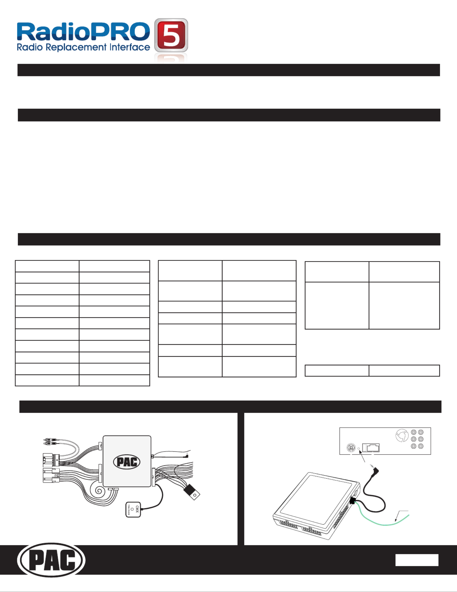
RP5-GM51
| Mærke: | PAC |
| Kategori: | Ikke kategoriseret |
| Model: | RP5-GM51 |
Har du brug for hjælp?
Hvis du har brug for hjælp til PAC RP5-GM51 stil et spørgsmål nedenfor, og andre brugere vil svare dig
Ikke kategoriseret PAC Manualer
11 Juli 2025
11 Juli 2025
10 Juli 2025
10 Juli 2025
30 Juni 2025
10 Marts 2025
19 Februar 2025
19 Februar 2025
19 Februar 2025
19 Februar 2025
Ikke kategoriseret Manualer
- Moen
- Kambrook
- Jan Nowak
- Schütte
- Canicom
- Phonak
- CRU
- Auna
- Eurolite
- Acros
- Hartke
- Perel
- Smoby
- Dragon Touch
- Johnson
Nyeste Ikke kategoriseret Manualer

11 December 2025

11 December 2025

11 December 2025

11 December 2025

11 December 2025

11 December 2025

11 December 2025

11 December 2025

11 December 2025

11 December 2025