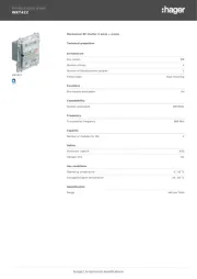
Hager WBMDUR Manual

Hager Vægudtag WBMDUR

Læs gratis den danske manual til Hager WBMDUR (2 sider) i kategorien Vægudtag. Denne vejledning er vurderet som hjælpsom af 2 personer og har en gennemsnitlig bedømmelse på 5.0 stjerner ud af 1.5 anmeldelser. Har du et spørgsmål om Hager WBMDUR, eller vil du spørge andre brugere om produktet?

Side 1/2
6LE007713B
01
WBMDUR
Rotary dimmer
Hager Electro Pty. Ltd., Unit 17/2-8 South Street, RYDALMERE NSW 2116, AUSTRALIA
The terminal block must be mounted in either
its original shipped position or on the rear of the
module by means of the enclosed cable tie.
(2) Retaining lugs for Rotoloc
®
fastening
(3) Connection cable
(4) Terminal block
Function
Correct use
- Switching and dimming of incandescent lamps,
HV halogen lamps and dimmable 230 V LED
lamps; electronic transformers with low voltage
halogen lamps.
- Unsuitable for fans and motors
- Suitable for indoor use only, but no drip and no
spray water.
- Suitable for Hager Rotoloc switch plates only
Product characteristics
- Phase cut-o󰀨 dimmers
- Wide dimming range down to the lowest
brightness for many lamps
- Programmable minimum brightness
- Additional congurable functions
- Automatic storage of the switch-o󰀨 brightness
level as switch-on brightness level
- Electronic short circuit, overload and thermal
protection
- Multi-way dimming available only with use of
the WBMSLL slave mechanisms
- Non volatile device settings
Control
Fig. 3: Rotary dimmer operation
Load
state
Action Result
OFF Short press
rotary knob
Switch with saved ON
switch-on brightness
level.
> 0% Short press
rotary knob
Switch and save OFF
brightness as switch-
on brightness level.
> 0% Turn rotary knob
anticlockwise
Dim down the light.
> 0% Turn rotary knob
clockwise
Dim up the light.
Table 1: Rotary dimmer operation
Fig. 4: Optional slave unit operation
Load
status
Action Result
OFF Short
press of
push-
button
Switch with saved switch-ON
on brightness level.
> 0% Short
press of
push-
button
Switch and save bright-OFF
ness as switch-on brightness
level.
> 0% Long
press of
button
With every long push-
button operation within 12 sec:
Dimming with alternating direc-
tion, otherwise device will dim
up, until max. level is reached.
Table 2: Operation on slave unit / push-button
Adjusting the minimum brightness for the
rotary dimmer
The minimum brightness level can be adjusted to
prevent poor switch-on behaviour or ickering of
the load in the lower dimming range.
Switch o󰀨 load.
Press and hold rotary knob for approx 10
seconds.
The load will ash once after 3 seconds and
then ash a second time after 10 seconds.
Release the rotary knob.
The device is in ne adjustment mode for the
minimum brightness level and the lamp is
switched on at the minimum brightness level.
Depending on the lamp, the minimum bright-
ness level of the lights installed may be too
low and the lights may appear o󰀨, gradually
increase the brightness level by rotating the
knob clockwise.
If no actions are performed within 10 seconds,
the dimmer exits programing operation.
Gradually turn the rotary knob anticlockwise.
This reduces the minimum brightness.
Gradually turn the rotary knob clockwise.
This increases the minimum brightness.
Once desired min lighting level is reached, wait
10 seconds for device to store the setting.
The load will be switched o󰀨, the dimmer re-
turns to normal operation.
Congurable additional functions
The additional functions can be congured by
pressing the rotary dimmer for the required number
of times.
Kick-start
A short voltage burst when lamp is initially turned
on to support lamp start-up.
Reduced maximum brightness
A non-adjustble voltage reduction for suppressing
ickering at maximum brightness.
Recovering the previous load state when power
is restored after a power cut
The status of the load prior to power loss will be
restored at power-on.
Conguration additional functions
Switch o󰀨 load.
Press and hold rotary knob for approx 10
seconds.
The load will ash once after 3 seconds and
then ash a second time after 10 seconds.
Release the rotary knob.
The device is in ne adjustment mode for the
minimum brightness level and the lamp is
switched on at the minimum brightness level.
Safety instructions
Electrical equipment must only be installed and
assembled by a qualied electrician in accord-
ance with the relevant installation standards,
guidelines, regulations, directives, safety and ac-
cident prevention regulations of the country.
Failure to comply with these instructions may re-
sult in damage to the device, re or other hazards.
Hazard due to electric shock. The device is not
suitable for safe disconnection of the mains sup-
ply. Even when the device is switched o󰀨, the
load is not isolated from the mains supply.
Do not connect non-dimmable lamps, their trans-
formers or operating devices. Observe manufac-
turer's data.
These instructions are an integral component of
the product and must be retained by the end user.
Design and layout of the device
(2)
(1)
(3)
Fig. 1: Front view
(2)
(3)
(4)
Fig. 2: Rear view
02 T +61 1300 850 253 F +61 1300 424 372 customerservice@hagerelectro.com.au hager.com - 12.2021
Press rotary knob again for approx. 3 s or more
until the load  ashes once.
Release the rotary knob.
Select the additional program function required
by pressing the rotary knob slowly, waiting for
the load to  ash after each press (selected from
Table 3) before pressing again.
After approx. 10 s without operation, the change
of additional function is stored and the device
switches to standard operation.
Con gurable
additional
functions
Factory
setting
Number of times
the rotary knob is
pressed
Kick-start OFF
1 x
Reduced
maximum
brightness
OFF
2 x
Recovery of the
load state when
the power is
restored
OFF
4 x
Table 3: Con gurable additional functions
Reset to factory setting
Switch o󰀨 load.
Press and hold rotary knob for approx 10
seconds.
The load will  ash once after 3 seconds and
then  ash a second time after 10 seconds.
Release the rotary knob.
The device is in  ne adjustment mode for the
minimum brightness level and the lamp is
switched on at the minimum brightness level.
Press and hold rotary knob again for approx 10
seconds.
The load will  ash once after 3 seconds and
then  ash a second time after 10 seconds.
Release the rotary knob.
The reset has been completed, the load is
switched o󰀨 and the dimmer is in standard op-
eration with the factory settings being e󰀨 ective.
Information for electricians
Installation and electrical connection
DANGER!
Electrical shock when live parts are
touched!
An electric shock can lead to death!
Isolate all power before working on
the device and cover any live parts in
the area!
ç
Connection diagram
A
N
Active / L
Load /
Remote
WBMDUR
Remote cable.
Not required for
1 way switched
dimming.
Fig. 5: 1 way connection
WBMSLL
A
N
Active / L
Load /
Remote
to additional
Slaves
WBMSLL
Active / L
Neutral
Remote
WBMDUR
Fig. 6: 2 way connection
Load side of device is not considered isolated in
OFF position.
Install a circuit breaker of max. 10 A as device
protection.
For 2 way or multiple way switching. Refer to
WBMSLL instructions.
Appendix
Technical data
Operating voltage 230 V~ +/-10%
Frequency 50 Hz
Miniature circuit breakers max. 10 A
Degree of protection IP2X
Standby power consumption < 0.07 W
230 V incandescent lamps,
halogen lamps and cold-light
re ector lamps
7 300 W
Dimmable, electronic
transformers with low voltage
halogen lamps
20 350 W
Dimmable 230 V LED lamps 3 ... 250 W
Slave units cable length
Load and slave unit cable
- in one cable
- in separate cables
max. 20 m
max. 50 m
Terminal block cables max. 2 x 1.5 mm²
max. 1 x 2.5 mm²
Flying leads,  exible 100 mm x 1,5 mm²
Operating temperature -5 to 50 °C
Storage temperature -20 to 70 °C
Relative humidity (without
dewing)
0 65 %
Operating conditions
Load type Maximum output
power (W)
25 °C 35 50 °C
Ohmic loads 300 265 210
Dimmable, electronic
transformers with low
voltage halogen lamps
350 310 250
230 V LED lamps 250 220 175
Table 4: Reduced performance, ambient temperature
When operating dimmers in combination with oth-
ers beneath a cover plate, the maximum connect-
ed load must be reduced depending on the number
of dimmers.
Number of dimmers per
combination
Connect load reduction
1 100%
2 75%
3 55%
4 40%
5 35%
6 30%
Table 5: Dimmer combination load reduction
Carry out loading of conventional, electronic
transformers according to manufacturer's
instructions.
Do not use non-dimmable 230 V LED lamps.
If 230 V LED lamps are used, the power supply
to the dimmer can cause the lamp to glow
slightly even when it is switched o󰀨 .
Troubleshooting
Dimmer switches o󰀨 of its own accord.
The electronic overload protection has tripped.
Check the load connected (excessive load).
Reduce the number of lamps or use lamps with
a lower power rating.
The electronic short-circuit protection has tripped.
Check electrical installation.
The load cannot be dimmed down suffi ciently.
The dimming angle is set too high.
Decrease the value in  ne-setting of the mini-
mum brightness.
The load switches o󰀨 while being dimmed
down.
The dimming angle is set too low.
Increase the value in  ne-setting of the mini-
mum brightness.
The load does not switch on.
The dimming angle and brightness value are set
too low.
Increase the value in  ne-setting of the mini-
mum brightness.
Load fl ickers while switched o󰀨 .
LED load too low.
Increase LED load at output.
The connected load cannot be dimmed or load
ickers while switched ON.
Lamps are not suitable for dimming.
Be sure always to use dimmable loads.
Unde ned fault during operation.
Slave unit cable length is too long or no separate
slave unit cable has been used.
Keep to slave unit cable length or, if necessary,
use separate slave unit cable.
Note:
LED loads should be tested with this dimmer
prior to installation. Some LED loads may not be
compatible due to the type of LED driver within the
LED light.
End of life treatment of electrical/
electronic equipment and batteries
in the European Union countries.
The crossed-out ‘wheeled bin symbol’ marked on
the equipment or its packaging, indicates that this
product is not to be disposed off with unsorted
municipal / household waste. Please check with
your local authority or retailer for recycling and
collection advice. This will enable you to contribute
to the disposal, treatment and recycling in an
environmentally sound way and help to prevent
potential negative effects on the environment and
human health.


Produkt Specifikationer

Mærke: Hager
Kategori: Vægudtag
Model: WBMDUR

Har du brug for hjælp?

Hvis du har brug for hjælp til Hager WBMDUR stil et spørgsmål nedenfor, og andre brugere vil svare dig