Theben LUXORliving R718 Manual

Theben Fjernbetjening LUXORliving R718

Læs gratis den danske manual til Theben LUXORliving R718 (6 sider) i kategorien Fjernbetjening. Denne vejledning er vurderet som hjælpsom af 7 personer og har en gennemsnitlig bedømmelse på 4.7 stjerner ud af 4 anmeldelser. Har du et spørgsmål om Theben LUXORliving R718, eller vil du spørge andre brugere om produktet?

Side 1/6
Hotline Theben:
J +49 7474 692-369
Theben AG | Hohenbergstraße 32 | 72401 Haigerloch | GERMANY | Telefon +49 7474 692-369 | info@theben.de | www.theben.de
21.09.2023307305 03
LUXORliving R718
4800480
ATENÇÃO
Perigo de morte por choque eléctrico ou
A montagem deve ser efectuada apenas por
um electricista especializado!
Antes da montagem/desmontagem activar a
tensão de rede!
Para outras descrições de funções, consulte o
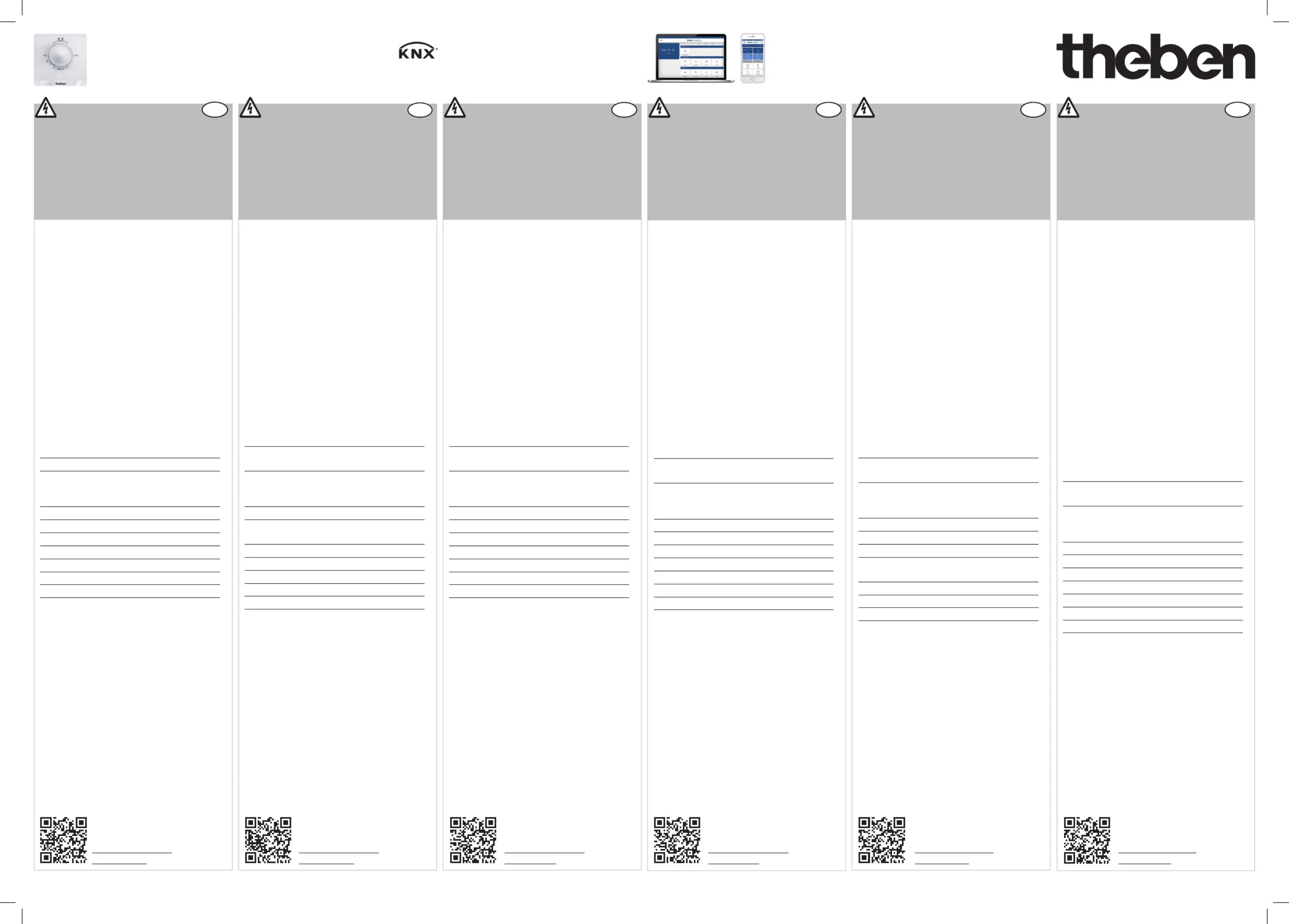
manual LUXORliving.
PT
Informações gerais
O regulador de temperatura ambiente da
série LUXORliving está em conformidade com
a norma EN 60730-2-9, em caso de monta-
gem correcta
Corresponde ao tipo 1 de acordo com
IEC/EN 60730-1
O LUXORliving R718 pode ser operado manu-
almente
Para controlo do aquecimento/ventilação em
instalações LUXORliving
4 Entradas binárias
Colocação em funcionamento com o software
LUXORplug e operação fácil com a App
LUXORplay (para Android e iOS):
www.LUXORliving.co.uk
Em caso de utilização num sistema KNX, a
programação ocorre com o ETS
Dados técnicos
Tensão de barramento: 21–32 V CC
Corrente absorvida barramento KNX:x. 12 mA
Escala de medição da temperatura:
–5 °C ... + 45 °C
I1-I4: tensão de contacto: 5 V SELV
méd. corrente de contacto: 0,5 mA
corrente máx. de contacto: 5 mA
Comprimento máx. do cabo: 30 m
Tipo de proteção: IP 20 conforme a EN 60529
Classe de protecção: III
Temperatura operacional: + 5 °C ... + 40 °C
Tensão transitória de dimensionamento: 0,8 kV
Grau de poluição: 2
Classe de software: A
Utilização correta
O regulador de temperatura mede a tempera-
tura; compara a temperatura ambiente atual
nas divisões residenciais e de escritórios
com o ajuste da temperatura e comanda os
aparelhos de aquecimento e de refrigeração
de acordo com as necessidades (por exemplo,
radiador ou tetos refrigerados)
Para aplicação tanto em residências como
em pequenos edifícios empresariais e de
escritórios
Pode aceder ao banco de dados ETS em
www.theben.de.
AVERTISSEMENT
Danger de mort, risque d‘électrocution et
d‘incendie!
Le montage doit être effectué exclusivement
par un électricien spécialisé!
Désactiver la tension réseau avant le monta-
ge/ le démontage !
Pour d'autres descriptions de fonction, se
reporter au manuel LUXORliving.
FR
Informations générales
Le régulateur de température ambiante
de la série LUXORliving répond à la norme
EN 60730-2-9 si le montage est conforme
Correspond au type 1 selon CEI/EN 60730-1
LUXORliving R718 peut être commandé
manuellement
Pour la commande du chauffage/de la clima-
tisation dans des installations LUXORliving
4 entrées binaires
Mise en service avec LUXORplug et comman-
de aisée par le biais de l'appli LUXORplay
(pour Android et iOS) : www.LUXORliving.fr
En cas d'intégration dans un système KNX, la
programmation s'opère via l'ETS
Caractéristiques techniques
Tension du bus : 21–32 V CC
Courant absorbé du bus KNX : max. 12 mA
Plage de mesure de la température : –5 °C ...
+ 45 °C
I1-I4 : tension de contact : 5 V TBTS
Courant de contact moyen : 0,5 mA
Courant de contact max. : 5 mA
Longueur de câble max. : 30 m
Indice de protection : IP 20 selon EN 60529
Classe de protection : III
Température de service : + 5 °C ... + 40 °C
Tension assignée de tenue aux chocs : 0,8 kV
Degré de pollution : 2
Classe de logiciel : A
Usage conforme
Le régulateur de la température ambian-
te mesure la température ; il compare la
température ambiante dans les pièces à vivre
et les bureaux à la température de consigne
réglée et commande les systèmes de chauf-
fage et de climatisation (par ex. radiateurs ou
plafonds réfrigérés) en conséquence
Pour utilisation dans des bâtiments privés,
plurifonctionnels et de bureaux
La base de données ETS est disponible à
l'adresse suivante www.theben.de.
AVVERTIMENTO
Pericolo di morte per scosse elettriche o
Il montaggio deve essere eseguito esclusi-
vamente da parte di un elettroinstallatore
specializzato!
Prima del montaggio o dello smontaggio
scollegare la tensione di rete!
Per maggiori descrizioni del funzionamento
fare riferimento al manuale LUXORliving.
IT
Informazioni generali
Il regolatore di temperatura della serie
LUXORliving è conforme alla norma EN
60730-2-9 se montato in modo conforme
Corresponde al tipo 1 según IEC/EN 60730-1
Il LUXORliving R718 può essere azionato
manualmente
Per il controllo di riscaldamento/climatizzazi-
one in impianti LUXORliving
4 ingressi binari
Messa in funzione con il software LUXORplug
e utilizzo semplice grazie all'applicazione
LUXORplay (per Android e iOS):
www.LUXORliving.it
In caso di impiego in un sistema KNX, la
programmazione avviene tramite ETS
Dati tecnici
Tensione bus KNX: 21–32 V DC
Assorbimento di corrente bus KNX: max 12 mA
Campo di misurazione temperatura:
–5 °C ... + 45 °C
I1-I4: tensione di contatto: 5 V SELV
interm. corrente di contatto: 0,5 mA
max. corrente di contatto: 5 mA
Lunghezza cavo max.: 30 m
Tipo di protezione: IP 20 secondo EN 60529
Classe di protezione: III
Temperatura d'esercizio: + 5 °C ... + 40 °C
Sovratensione transitoria nominale: 0,8 kV
Grado di inquinamento: 2
Classe software: A
Uso conforme
Il regolatore della temperatura ambiente
misura la temperatura; confronta la tempe-
ratura ambiente attuale nell'abitazione o in
ufcio con la temperatura nominale imposta-
ta e controlla gli apparecchi di riscaldamento
e raffreddamento in base al fabbisogno (per
es. radiatori o impianto di raffrescamento a
softto)
Per l'uso nell'edilizia abitativa privata, piccoli
ufci e edici commerciali
La banca dati ETS si trova su
www.theben.de.
ADVERTENCIA
¡Peligro de muerte por descarga elétrica o
¡El montaje debe ser llevado a cabo exclusiva-
mente por un electricista profesional!
¡Desconecte la tensión de red, antes de pro-
ceder al montaje o desmontaje!
Descripciones de función adicionales en el
manual LUXORliving.
ES
Información general
El regulador de temperatura ambiente de la
serie LUXORliving se corresponde con
EN 60730-2-9 cuando el montaje se realiza
correctamente
Corresponde al tipo 1 según IEC/EN 60730-1
LUXORliving R718 puede manejarse manu-
almente
Para el control de la calefacción/refrigeración
en instalaciones LUXORliving
4 entradas binarias
Puesta en servicio con el software LUXORplug
y manejo sencillo con la App LUXORplay (para
Android e iOS): www.LUXORliving.es
Al utilizar un sistema KNX, la programación se
realiza con el ETS
Datos técnicos
Tensión de bus: 21–32 V CC
Consumo de corriente del bus KNX: máx. 12 mA
Gama de medida de temperatura:
–5 °C ... + 45 °C
I1-I4: tensión de contacto: 5 V SELV
Med. corriente de contacto: 0,5 mA
Máx. corriente de contacto: 5 mA
Longitud máx del cable: 30 m
Grado de protección: IP 20 según EN 60529
Clase de protección: III
Temperatura de funcionamiento:
+ 5 °C ... + 40 °C
Impulso de sobretensión admisible: 0,8 kV
Grado de polución: 2
Clase de software: A
Uso previsto
El regulador de temperatura ambiente mide
la temperatura. Compara la temperatura
ambiente actual en viviendas y espacios de
ocinas con la temperatura nominal ajustada,
y controla en función de las necesidades los
aparatos de calefacción y refrigeración (p. ej.
radiadores o techos refrigerantes)
Para la utilización en viviendas privadas y
en pequeños edicios de ocinas y edicios
funcionales
Encontrará la base de datos ETS en
www.theben.de.
WARNUNG
Lebensgefahr durch elektrischen Schlag oder
Brand!
Montage ausschließlich von Elektrofachkraft
durchführen lassen!
Vor Montage/Demontage Netzspannung
freischalten!
Weitere Funktionsbeschreibungen im
LUXORliving-Handbuch.
DE
Allgemeine Infos
Der Raumtemperaturregler der LUXORliving-
Serie entspricht EN 60730-2-9 bei bestim-
mungsgemäßer Montage
Gerät entspricht Typ 1 nach IEC/EN 60730-1
LUXORliving R718 kann manuell bedient
werden
Zur Steuerung von Heizung/Kühlung in
LUXORliving-Anlagen
4 Binäreingänge
Inbetriebnahme mit der Software LUXORplug
und einfache Bedienung mit der App
LUXORplay (für Android und iOS):
www.LUXORliving.de
Bei Verwendung in einem KNX-System erfolgt
die Programmierung mit der ETS
Technische Daten
Busspannung KNX: 21–32 V DC
Stromaufnahme KNX-Bus: max. 12 mA
Messbereich Temperatur: –5 °C ... + 45 °C
I1-I4: Kontaktspannung: 5 V SELV
mittl. Kontaktstrom: 0,5 mA
max. Kontaktstrom: 5 mA
Max. Kabellänge: 30 m
Schutzart: IP 20 nach EN 60529
Schutzklasse: III
Betriebstemperatur: + 5 °C ... + 40 °C
Bemessungsstoßspannung: 0,8 kV
Verschmutzungsgrad: 2
Softwareklasse: A
Bestimmungsgemäße Verwendung
Der Raumtemperaturregler misst die Tem-
peratur; er vergleicht die aktuelle Raum-
temperatur in Wohn- und Büroräumen mit
der eingestellten Solltemperatur und steuert
gemäß Bedarf Heiz- und Kühlgeräte (z. B.
Heizkörper oder Kühldecken)
Für den Einsatz im privaten Wohnbau und in
kleineren Büro- und Zweckgebäuden
Die ETS-Datenbank finden Sie unter
www.theben.de.
Mais informações
http://qr.theben.de/
p/ pt4800480
Informations supplémentaires
http://qr.theben.de/
p/4800480fr
Maggiori informazioni
http://qr.theben.de/
p/4800480it
Información adicional
http://qr.theben.de/
p/ es4800480
Weitere Informationen
http://qr.theben.de/
p/4800480de
Further information
http://qr.theben.de/
p/4800480en
LUXORplayLUXORplug
LUXORliving
WARNING
Danger of death through electric shock or
re!
Installation should only be carried out by
professional electrician!
Disconnect the mains power supply prior to
installation and/or disassembly!
Further functional descriptions in the
LUXORliving handbook.
EN
General information
The room temperature controller of the
LUXORliving series conforms with EN 60730-
2-9 if correctly installed
Corresponds to type 1 in accordance with
IEC/EN 60730-1
LUXORliving R718 can be operated manually
For heating/cooling control in LUXORliving
systems
4 binary inputs
Start-up using the LUXORplug software and
easy operation using the LUXORplay app (for
Android and iOS): www.LUXORliving.co.uk
When used in a KNX system, programming is
completed with the ETS
Technical data
Bus voltage KNX: 21–32 V DC,
Power input KNX bus: max. 12 mA
Measurement range temperature: –5 °C ... +
45 °C
I1-I4: contact voltage: 5 V SELV
aver. contact current: 0.5 mA
max. contact current: 5 mA
Max. cable length: 30 m
Protection rating: IP 20 in accordance with
EN 60529
Protection class: III
Operating temperature: + 5 °C ... + 40 °C
Rated impulse voltage: 0.8 kV
Pollution degree: 2
Software class: A
Proper use
The room temperature controller measures
the temperature; it compares the current
room temperature in living and ofce rooms
with the set temperature, and controls accor-
ding to the demand of heating and cooling
devices (e.g. radiators or cooling ceilings)
For use in private buildings and in smaller
ofce and single-purpose buildings
The ETS database is available at
www.theben.de.
Montagem
Eletricidade estática! Cuidado, componentes
eletrónicos sensíveis! Durante a montagem
respeitar as medidas preventivas de des-
cargas de eletricidade estática (electrostatic
discharge).
! Colocar o regulador numa parede interior,
ao nível dos olhos (também possível no
encaixe embutido).
! Evitar correntes de ar ou a radiação de
calor.
! Não montar o regulador sobre uma superfí-
cie mole, caso contrário deixa de se vericar
renovação do ar.
¾ Fixar a placa de montagem à parede .
¾Encaixar e ligar o suporte das placas de
circuito impresso, isto é, passar o cabo de bus
através da abertura e encaixá-lo no borne de
barramento ; tendo atenção à polaridade;
se necessário, ligar a interface do sensor
¾Pendurar primeiramente a parte superior do
sensor em cima e, de seguida, encaixar .
¾Programar o endereço físico: premir a tecla
de programação (o LED de programação
acende). O aparelho está no modo de progra-
mação.
¾Voltar a colocar a cobertura .
Desmontagem
¾Soltar o painel frontal com uma chave de
parafusos em ambas as aberturas laterais e
inferiores .
¾De seguida, abrir os fechos à direita e à es-
querda e remover a parte superior da caixa .
¾Soltar os conectores e pressionar o suporte
de placas de circuito impresso em cima e em
baixo .
¾Remover para a frente o suporte de placas de
circuito impresso.
Ligação
! I1–I4: ligar apenas os contactos isolados.
! Atentar à muito baixa tensão/distâncias.
Operação
Com o controlo rotativo é regulada a tempe-
ratura nominal (5 °C – 30 °C).
O LED por baixo do controlo rotativo acende
quando o valor nominal do controlo rotativo e
do LUXORplay não são idênticos.
Com a tecla por baixo do controlo rotativo, os
LED podem ser ligados/desligados.
Montage
Décharge électrostatique ! Attention aux
composants électroniques sensibles ! Lors
du montage, respecter les mesures de
protection DES (décharge électrostatique).
! Placer le régulateur sur un mur intérieur, à
hauteur des yeux (également possible sur
un boîtier encastré).
! Éviter les courants d'air ou le rayonnement
thermique.
! Ne pas monter le régulateur sur une surface
molle, car elle empêcherait tout échange
d'air.
¾ Fixer la plaque de montage au mur .
¾Enclencher et câbler le support de circuit
imprimé, cela signie passer le câble de
bus à travers l'ouverture et l'encher dans
le bornier pour bus ; vérier pour cela la
polarité ; raccorder l'interface pour boutons-
poussoirs si nécessaire
¾Suspendre tout d'abord la partie supérieure
de la sonde en haut, puis l'enclencher .
¾Programmer l'adresse physique : appuyer
sir la touche de programmation (la LED de
programmation s'allume). L'appareil est en
mode de programmation.
¾ Replacer le cache .
Démontage
¾Détacher la plaque frontale en insérant un
tournevis dans les deux orices latéraux
inférieurs .
¾Ouvrir ensuite les xations droite et gauche
et retirer la partie supérieure du boîtier .
¾Détacher les connecteurs et comprimer la
partie haute et la partie basse du support de
circuits imprimés .
¾Retirer le support de circuits imprimés par
l'avant.
Raccordement
! I1–I4 : uniquement raccorder des contacts
libres de potentiel.
! Tenir compte de la très basse tension de
sécurité / des distances.
Utilisation
La bague rotative permet de régler la tem-
pérature de consigne (5 °C – 30 °C).
La LED en dessous de la bague rotative
est allumée si les valeurs de consigne de la
bague rotative et du LUXORplay ne sont pas
identiques.
La touche en dessous de la bague rotative
permet d'activer/de désactiver les LED.
Montaggio
Carica elettrostatica! Attenzione compo-
nenti elettronici sensibili! Durante il mon-
taggio osservare le misure di protezione
ESD (electrostatic discharge).
! Collocare il regolatore su una parete inter-
na, circa all'altezza degli occhi (è possibile
anche il montaggio ad incasso).
! Evitare correnti d'aria o irraggiamenti di
calore.
! Non montare il regolatore su un supporto
morbido, perché impedirebbe il ricircolo
d'aria.
¾Fissare la piastra di montaggio sulla parete .
¾Inserire e cablare il supporto scheda, vale
a dire far passare la linea bus attraverso
l'apertura e inserirlo nel morsetto bus ;
prestare attenzione alla polarità; collegare
eventualmente l'interfaccia tasti
¾La parte superiore del sensore va prima
agganciata in alto e poi ssata .
¾Programmare l'indirizzo sico: premere il
tasto di programmazione (il LED di program-
mazione si illumina). L'apparecchio si trova in
modalità di programmazione.
¾Applicare la copertura .
Smontaggio
¾Con un cacciavite staccare la piastra frontale
agendo su entrambe le aperture laterali ed
inferiori .
¾Aprire successivamente le chiusure destra
e sinistra e rimuovere la parte superiore
dell'involucro .
¾Staccare il connettore ad innesto e premere
insieme in alto ed in basso il supporto del
circuito stampato .
¾Togliere estraendolo dal davanti il supporto
del circuito stampato.
Collegamento
! 1–I4: collegare solo contatti a potenziale
zero.
! Osservare la bassa tensione di sicurezza/
le distanze.
Utilizzo
Con la rotellina è possibile regolare la tempe-
ratura nominale (5 °C - 30 °C).
Il LED sotto la rotellina si illumina quando il
valore nominale della rotellina non è identico
a quello del LUXORplay.
Con il tasto sotto la rotellina è possibile
accendere e spegnere i LED.
Montaje
¡Carga electrostática! ¡Cuidado, compo-
nentes electrónicos sensibles! Durante el
montaje, observar las medidas de protección
ESD (electrostatic discharge).
! Colocar el regulador en una pared interior,
aprox. a la altura de los ojos (también pue-
de ser en una caja empotrada).
! Evitar corrientes de aire o radiaciones de
calor.
! No montar el regulador en una base blanda,
ya que, si no, no se puede producir ningún
intercambio de aire.
¾ Fijar la placa de montaje a la pared .
¾Encajar y cablear el soporte de la placa de
circuitos, es decir, guiar la línea de bus a
través de la abertura e introducir en el borne
de bus ; al hacerlo tener en cuenta la po-
laridad. Si es necesario, conectar una interfaz
de teclado
¾Enganchar primero arriba la parte superior
del sensor y a continuación encajar .
¾Programar la dirección física: pulsar la tecla
de programación (el LED de programación se
enciende). El aparato se encuentra en modo
programación.
¾ Colocar la cubierta .
Desmontaje
¾Con un destornillador soltar la placa frontal
en ambos oricios laterales y en la parte
inferior .
¾A continuación abrir a derecha e izquierda los
enclavamientos y retirar la parte superior de
la carcasa .
¾Soltar los conectores y apretar el soporte de
la placa de circuitos arriba y abajo .
¾Retirar el soporte de la placa de circuitos
hacia delante.
Conexn
! I1–I4: conectar solo contactos sin potencial.
! Observar la baja tensión de protección /
distancias.
Manejo
Con la rueda de selección se ajusta la tempe-
ratura nominal (5 °C – 30 °C).
El LED debajo de la rueda de selección se
enciende, cuando el valor nominal de la rueda
de selección y LUXORplay no son idénticos.
La tecla debajo de la rueda de selección
permite encender/apagar los LED.
Montage
Elektrostatische Auadung! Vorsicht
empndliche elektronische Bauteile!
Bei der Montage ESD-Schutzmaßnahmen
(electrostatic discharge) beachten.
! Den Regler an einer Innenwand, etwa auf
Augenhöhe platzieren (auch auf Unterputz-
Dose möglich).
! Zugluft oder Wärmeabstrahlung vermeiden.
! Regler nicht auf einer weichen Unterlage
montieren, da sonst kein Luftaustausch
stattnden kann.
¾Montageplatte an der Wand befestigen .
¾Leiterplattenträger einrasten und verdrahten,
d. h. Busleitung durch die Öffnung führen
und in die Busklemme stecken ; dabei auf
die Polarität achten; ggf. Tasterschnittstelle
anschließen.
¾Oberen Teil des Sensors zuerst oben einhän-
gen und danach einrasten .
¾Physikalische Adresse programmieren: Die
Programmiertaste drücken (die Programmier-
LED leuchtet). Gerät ist im Programmiermodus.
¾ Abdeckung aufsetzen .
Demontage
¾Mit einem Schraubendreher an den beiden
seitlichen und unteren Öffnungen Frontplatte
lösen .
¾Danach rechts und links Verrastungen öffnen
und das Gehäuseoberteil abnehmen .
¾Steckverbinder lösen und Leiterplattenträger
oben und unten zusammendrücken .
¾Leiterplattenträger nach vorne entnehmen.
Anschluss
! I1–I4: nur potenzialfreie Kontakte anschlie-
ßen.
! Schutzkleinspannung/Abstände beachten.
Bedienung
Mit dem Drehrad wird die Solltemperatur
(5 °C – 30 °C) eingestellt.
Die LED unterhalb des Stellrades leuchtet,
wenn der Sollwert von Stellrad und LUXOR-
play nicht identisch sind.
Mit der Taste unterhalb des Stellrades können
die LEDs ein-/ausgeschaltet werden.
DE
Installation/Dismounting
Operating mode heating/cooling
(frost and heat protection)
Button for LED Off; LED lits orange if
temperature has been modied in the app
LUXORplay
Meaning of LEDs and buttons
LED/button
(from top to
bottom)
Display Colour operable
1
Status of room tem-
perature controller
(heating, cooling)
red (heating)
blue (cooling)
2 Button LED OFF
green
rotary knob = set point
orange
rotary knob <> set point
x
Rotary knob for
frost protection
set point of 5 °C – 30 °C congurable
blue/white
blue
brown/white
brown
red/white
red
green/white
green
Programming button and LED for physical
address (under the cover)
Connection/inputs
Installation
Electrostatic discharge! Caution: sensitive
electronic components! When tting, ob-
serve ESD safety measures (electrostatic
discharge).
! Position the controller on an internal wall,
at about eye level (also possible on ush-
mounting box).
! Avoid drafts or heat emission.
! Do not not mount the controller on a soft
surface, as this will inhibit air exchange.
¾ Attach the mounting plate at the wall .
¾Engage and wire the circuit board carrier,
i.e. lead the bus line through the opening
and plug it into the bus terminal ; obser-
ve the polarity; connect button interface as
appropriate
¾Hook in the upper part of the sensor rst,
then engage .
¾Programming the physical address: Push the
programming button (the programming LED
is lit). Device is in programming mode.
¾ Put on the cover .
Dismounting
¾Using a screwdriver, loosen the front panel
via the two side and bottom openings .
¾Then release the catches on the left and right
and remove the upper part of the housing .
¾Loosen the plug-in connectors and press the
circuit board carrier together at the top and
bottom .
¾Remove the circuit board carrier through the
front.
Connection
! I1–I4: Only connect oating contacts.
! Observe extra-low voltage/distances.
Operation
The rotary knob is used to set a set tempera-
ture (5 °C – 30 °C).
The LED under the rotary knob lights up if
the rotary knob and LUXORplay set values are
not identical.
The button under the rotary knob can be
used to switch the LEDs on and off.
EN FR IT ES
PT


Produkt Specifikationer

Mærke: Theben
Kategori: Fjernbetjening
Model: LUXORliving R718

Har du brug for hjælp?

Hvis du har brug for hjælp til Theben LUXORliving R718 stil et spørgsmål nedenfor, og andre brugere vil svare dig