Valcom Trunk Port VIP-824 Manual
Læs gratis den danske manual til Valcom Trunk Port VIP-824 (4 sider) i kategorien Netværkskort/adapter. Denne vejledning er vurderet som hjælpsom af 51 personer og har en gennemsnitlig bedømmelse på 4.9 stjerner ud af 26 anmeldelser.
Har du et spørgsmål om Valcom Trunk Port VIP-824, eller vil du spørge andre brugere om produktet?

Produkt Specifikationer
| Mærke: | Valcom |
| Kategori: | Netværkskort/adapter |
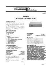
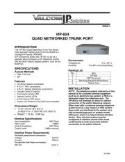
| Model: | Trunk Port VIP-824 |
| Bredde: | 171.5 mm |
| Dybde: | 241 mm |
| Højde: | 44.5 mm |
| Vægt: | 790 g |
| Produktfarve: | Grå |
| Relativ luftfugtighed ved drift (H-H): | 0 - 85 % |
| Ethernet LAN-porte (RJ-45): | 1 |
| Driftstemperatur (T-T): | 0 - 40 °C |
| Strømforsyningstype: | 24 VDC |
| Forbindelsesteknologi: | Ledningsført |
| Certificering: | FCC |
| Netværksstandarder: | IEEE 802.3af |
| Understøttede netværksprotokoller: | DHCP, IGMP v3, UDP, TCP, HTTP, Telnet, FTP |
| LED-indikatorer: | Ja |
| Værtsgrænseflade: | RJ-45 |
| Grænseflade: | Ethernet |
| Intern: | Ingen |
| Maksimal dataoverførselshastighed: | 100 Mbit/s |
| Indgangsstrøm: | 0.325 A |
| Stik: | 8 x RJ-11 |
| USB-drevet: | Ingen |
| Netværk klar: | Ja |
| Porte, antal: | 4 |
| Link/Act LED: | Ja |
Har du brug for hjælp?
Hvis du har brug for hjælp til Valcom Trunk Port VIP-824 stil et spørgsmål nedenfor, og andre brugere vil svare dig
Netværkskort/adapter Valcom Manualer


Netværkskort/adapter Manualer
- SIIG
- Kensington
- J5 Create
- Mede8er
- Gigaset
- Allied Telesis
- Topcom
- Luxul
- Aluratek
- D-Link
- Pinnacle
- Draytek
- Ferguson
- CLUB3D
- Code Corporation
Nyeste Netværkskort/adapter Manualer