Gira Sensotec LED Manual
Gira
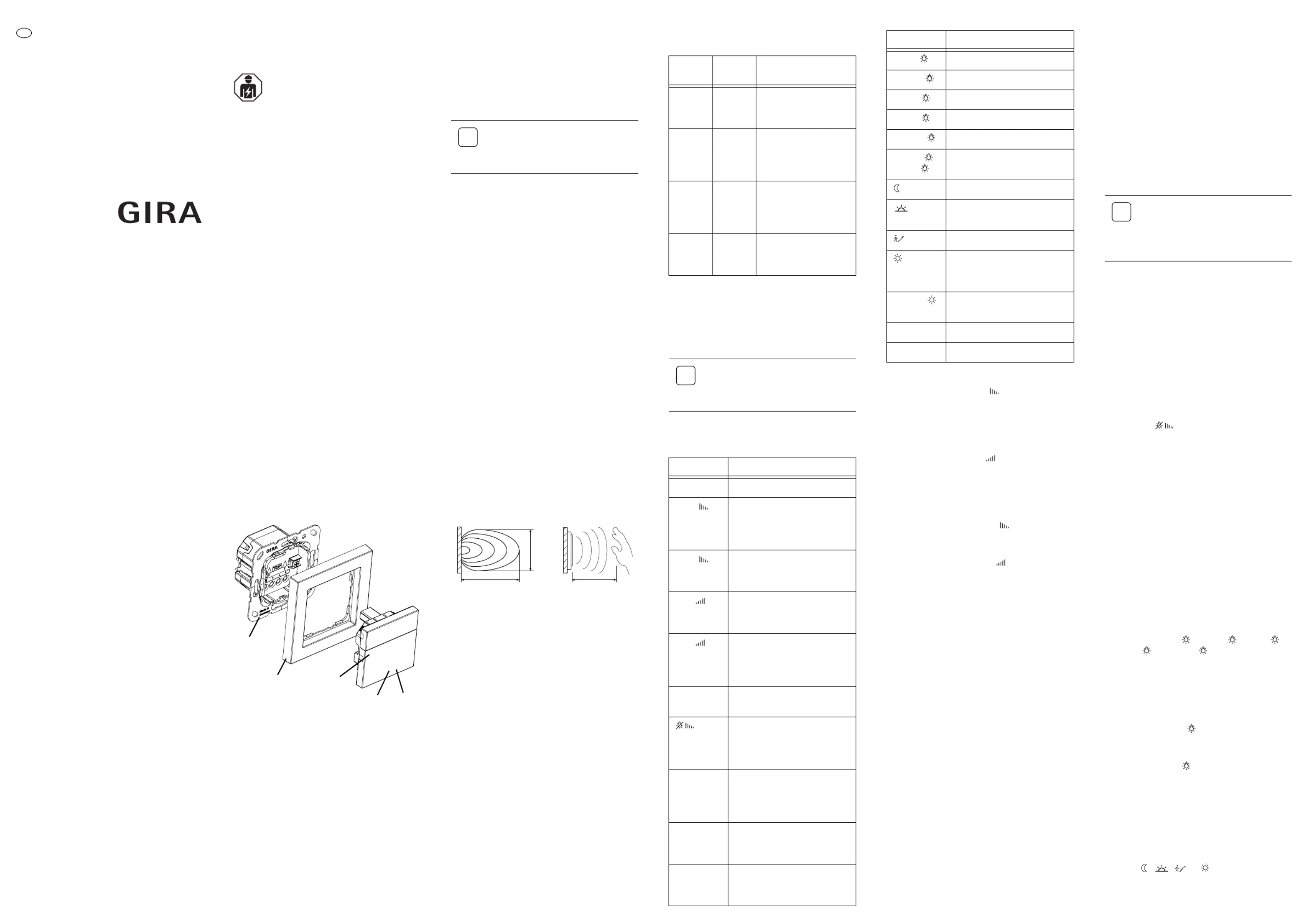
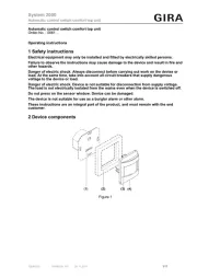
Bevægelsesdetektor
Sensotec LED
| Mærke: | Gira |
| Kategori: | Bevægelsesdetektor |
| Model: | Sensotec LED |
| Produktfarve: | Hvid |
| Driftstemperatur (T-T): | 0 - 50 °C |
| Forbindelsesteknologi: | Ledningsført |
| Placering: | Indendørs |
| LED-indikatorer: | Ja |
| Strømkilde type: | Vekselstrøm |
| Monteringstype: | Væg |
| Indgangsspænding: | 230 V |
| Sensortype: | Mikrobølgesensor |
| Indgangsfrekvens: | 50/60 Hz |
| Opdagelsesafstand: | 6 m |
| Installationshøjde (min.): | 1.1 m |
Har du brug for hjælp?
Hvis du har brug for hjælp til Gira Sensotec LED stil et spørgsmål nedenfor, og andre brugere vil svare dig
Bevægelsesdetektor Gira Manualer
22 Juli 2025
22 Juli 2025
5 August 2024
Bevægelsesdetektor Manualer
- Heath Zenith
- Yale
- Schneider
- EtiamPro
- Blaupunkt
- Chuango
- Gewiss
- Kopp
- Megatron
- Marmitek
- GEV
- Dahua Technology
- Bitron
- Biltema
- Chacon
Nyeste Bevægelsesdetektor Manualer

20 December 2025

18 December 2025

16 December 2025

11 December 2025

10 December 2025

10 December 2025

9 December 2025

9 December 2025

8 December 2025

7 December 2025