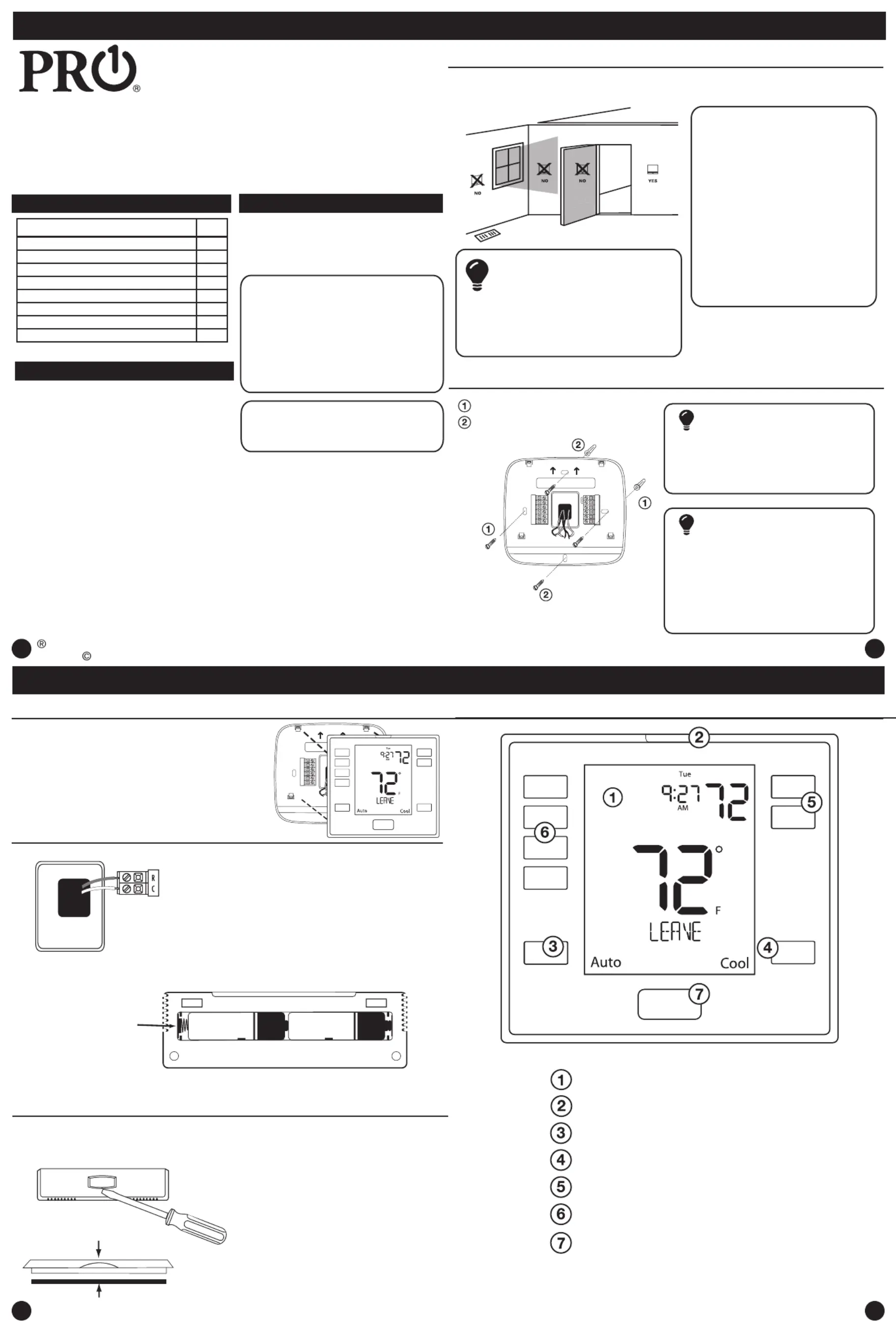
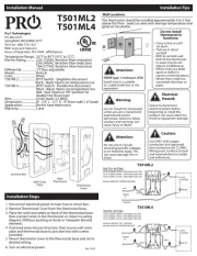
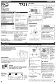
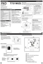
Pro1 T755S Manual

Pro1 Termostat T755S

Læs gratis den danske manual til Pro1 T755S (6 sider) i kategorien Termostat. Denne vejledning er vurderet som hjælpsom af 2 personer og har en gennemsnitlig bedømmelse på 4.4 stjerner ud af 1.5 anmeldelser. Har du et spørgsmål om Pro1 T755S, eller vil du spørge andre brugere om produktet?

Side 1/6
Set At
Menu
T755(S)
Installation Manual
Pro1 Technologies
Toll Free: 888-776-1427
Web: www.pro1iaq.com
Hours of Operation: M-F 9AM - 6PM Eastern
Power Type
Hardwire (Common Wire)
Hardwire (Common Wire) with
Battery Backup
A trained, experienced
technician must install this
product.
Carefully read these
instructions. You could damage
this product or cause a
hazardous condition if you fail to
follow these instructions.
Una version en español de este
manual se puede descargar en
la pagina web de la compañia.
Rev. 2212
U.S. Registered Trademark. Patents pending
Copyright 2022 All Rights Reserved.
1
1
1
1
Installation Tips
2
2
2
2
3
3
3
3
4
4
4
4
Installation Tips
Thermostat Application Guide
Description
Gas or Oil Heat
Electric Furnace
Heat Pump (No Aux. or Emergency Heat)
Heat Pump (With Aux. or Emergency Heat)
Multi-Stage Systems
Heat Only Systems
Cool Only Systems
Millivolt
Yes
Yes
Yes
Yes
Yes
Yes
Yes
Yes
Table of Contents
Installation Tips
Thermostat Quick Reference
Wiring
Wiring Diagrams
Features
Technician Setup
Programming Thermostat
Specications
Page
2-3
4-5
6
7-9
10
20-23
Subbase Installation
The thermostat should be installed approximately 4 to 5 feet above the
oor. Select an area with average temperature and good air circulation.
• Close to hot or cold air ducts
That are in direct sunlight
With an outside wall behind
the thermostat
• In areas that do not require
conditioning
Where there are dead spots
or drafts
(in corners or behind doors)
Where there might be
concealed chimneys or
pipes
Wall Locations
Vertical Mount
Horizontal Mount
For vertical mount put one screw on the top
and one screw on the bottom.
For horizontal mount put one screw on the
left and one screw on the right.
All of our products are mercury free.
However, if the product you are
replacing contains mercury, dispose of
it properly. Your local waste
management authority can give you
instructions on recycling and proper
disposal.
Pick an installation location that is easy for
the user to access. The temperature of the
location should be representative of the
building.
Installation Tip
Mercury Notice
Do not install
thermostat in locations:
Failure to disconnect the power before
beginning to install this product can
cause electrical shock or equipment
damage.
Installation Tip:
Electrical Hazard
Mount Thermostat
Align the 4 tabs on the subbase with
corresponding slots on the back of the
thermostat, then push gently until the
thermostat snaps in place.
Battery Installation
Getting to know your thermostat
Glow in the dark light button
Fan Button
System Button
Temperature Setpoint Buttons
User Buttons
Thermostat Quick Reference
11-19
LCD Display
P.O. Box 3377
Springeld, MO 65808-3377
Private Label Badge
Battery installation is optional if thermostat is
hardwired (R and C terminal connected to 24V
power).
Important:
High quality alkaline batteries are recommended.
Rechargeable batteries or low quality batteries
do not guarantee a 1-year life span.
Insert 2 AA
Alkaline batteries
(included). High
quality alkaline
batteries are
recommended.
Located ont p1-he back of the thermostat.
Gently slide a screwdriver into the
bottom edge of the badge. Gently turn
the screwdriver counter clockwise. The
badge is held on by a magnet in the well
of the battery door. The badge should pry
o easily. DO NOT USE FORCE.
About The Private Label Badge
All of our thermostats use the same universal magnetic badge. Visit the
company website to learn more about our free private label program.
Magnet in door
Use the bevel on lower ridge
Set At
Menu
24
Em.Heat
AutoCool
Set At
On LHM
Tech Set
Set Sched
Next
Run Sched
Set Time
Hold
Done
Menu
Prev
HOLD
STAGES
1+2+3
COOL ON
HEAT ON
FAN ON
Thermostat Quick Reference
The low battery indicator is displayed when the AA battery power is low. If the user
fails to replace the battery within 21 days, the screen will only show the low battery
indicator but maintain all functionality. If the user fails to replace the batteries after
an additional 21 days (days 22-42 since rst “low battery display) the setpoints will
change to 55˚F (Heating) and 85˚F (Cooling). If the user adjusts the setpoint away from
either of these, it will hold for 4 hours then return to either 55˚F or 85˚F. After day 63
the batteries must be replaced immediately to avoid freezing or overheating because
the thermostat will shut the unit o until the batteries are changed.
Important
Indicates the current room temperature
Time and day of the week
Setpoint: Displays the selected setpoint temperature.
Hold is displayed when the thermostat program is permanently overridden.
System Operation Indicators:
The COOL ON , HEAT ON or icon will display when the COOL, HEAT, or
(fan) is on. The compressor delay feature is active if these are ashing.
Low Battery Indicator: Replace batteries when this indicator is shown.
Menu Options: Shows dierent options.
Program Time Periods: This thermostat has 4 programmable time periods
per day.
Getting to know your thermostat
Wiring
5
5
5
5
6
6
6
6
7
7
7
7
8
8
8
8
Wiring Tips
C Terminal
The C (common wire) terminal does
not have to be connected when the
thermostat is powered by batteries.
Wire Specications
Use shielded or non-shielded
18-22 gauge thermostat wire.
Caution:
Electrical Hazard
All components of the control
system and the thermostat
installation must conform to Class II
circuits per the NEC Code.
Warning:
Installation Tip: Do not overtighten terminal block screws, as this
can damage the terminal block. A damaged terminal block can
keep the thermostat from tting on the subbase correctly or cause
system operation issues. Max Torque = 6in-lbs.
Wiring
If you are replacing a thermostat,
make note of the terminal
connections on the thermostat that
is being replaced. In some cases
the wiring connections will not be
color coded. For example, the green
wire may not be connected to the G
terminal.
Loosen the terminal block screws.
Insert wires then retighten terminal
block screws.
Place nonammable insulation into
wall opening to prevent drafts.
1.
2.
3.
Failure to disconnect the power
before beginning to install this
product can cause electrical shock
or equipment damage.
Power supply
Factory - installed jumper. Remove only when installing on a 2 transformer systems.
System: Indicates current mode of operation.
Note: This thermostat is
hardwire powered when the
24V transformer is
connected to the Common
and of the RC terminals
thermostat.
Use either O or B terminals for changeover valve.
Optional 24 VAC common connection when thermostat is used in battery power mode.
Terminal
2 Heat 2 Cool
Conventional
System
2 Heat 2 Cool
Heat Pump
System
3 Heat 2 Cool
Heat Pump
System
RC
RH
C
B
O
G
W/E
W2
Transformer power
(cooling)
Transformer power
(heating)
Transformer common
Energized in heating
Energized in cooling
Fan relay
First stage of heat
Second stage of heat
Transformer power
(cooling)
Transformer power
(heating)
Transformer common
Heat pump changeover
valve energized in heating
Fan relay
First stage of
emergency heat
Auxiliary heat relay,
second stage of heat
Heat pump changeover
valve energized in cooling
Transformer power
(cooling)
Transformer power
(heating)
Transformer common
Heat pump changeover
valve energized in heating
Fan relay
First stage of
emergency heat
Auxiliary heat relay,
third stage of heat
Heat pump changeover
valve energized in cooling
Wiring Diagrams
Stages: Stage 1 will appear on the display when the 1st stage of heat or
cool is on. +2 will appear on the display when the 2nd stage of heat or cool
is on. +3 will appear on the display when the 3rd stage of heat or cool is on.
Y
Y2
Second stage of cool
First stage of heat & cool
Second stage of cool
First stage of heat & cool
Second stage of cool
& second stage of heat
Note: In many systems
with no emergency heat
relay a jumper can be
used between E and W2.
1
2
3
7
8
1
2
3
7
8
Globe: Globe is displayed if an energy ecient temperature has been selected.
S1/S2
Remote Sensor Remote Sensor Remote Sensor
Typical 2H/2C System: 1 Transformer
Typical Heat Only System With Fan
Typical Cool-Only System With Fan
FAN RELAY
HEAT RELAY
RC
RH
Y
C
W/E
G
C
R
L2
L1(HOT)
FAN RELAY
COMPRESSOR
RELAY
C
R
L2
L1(HOT)
RC
RH
Y
C
G
W/E
RC
RH
Y
C
W/E
G
W2
Y2
COMPRESSOR
RELAY
FAN RELAY
HEAT RELAY 2
COMPRESSOR
RELAY 2
HEAT RELAY
C
R
L2
L1(HOT)
Note:
In many systems with no emergency heat relay a jumper can be installed
between W/E and W2.
Wiring Diagrams
Auto


Produkt Specifikationer

Mærke: Pro1
Kategori: Termostat
Model: T755S

Har du brug for hjælp?

Hvis du har brug for hjælp til Pro1 T755S stil et spørgsmål nedenfor, og andre brugere vil svare dig


Termostat Pro1 Manualer

Pro1

Pro1 T721 Manual

20 August 2025
Pro1

Pro1 T731WO Manual

20 August 2025
Pro1

Pro1 R251S Manual

20 August 2025
Pro1

Pro1 T805 Manual

20 August 2025
Pro1

Pro1 T701i Manual

20 August 2025
Pro1

Pro1 T721i Manual

20 August 2025
Pro1

Pro1 E219 Manual

20 August 2025
Pro1

Pro1 T701 Manual

20 August 2025
Pro1

Pro1 T755S Manual

20 August 2025
Pro1

Pro1 T501M Manual

20 August 2025

Termostat Manualer

Nyeste Termostat Manualer