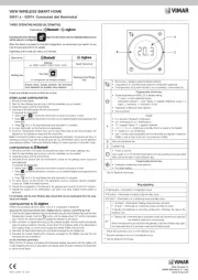
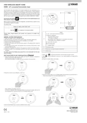
Vimar 14440.SL Manual

Vimar Termostat 14440.SL

Læs gratis den danske manual til Vimar 14440.SL (6 sider) i kategorien Termostat. Denne vejledning er vurderet som hjælpsom af 4 personer og har en gennemsnitlig bedømmelse på 4.3 stjerner ud af 2.5 anmeldelser. Har du et spørgsmål om Vimar 14440.SL, eller vil du spørge andre brugere om produktet?

Side 1/6
Viale Vicenza, 14
36063 Marostica VI - Italy
www.vimar.com
49400975A0 05 2203
PLANA
14440
Commutatore
condizionamento/riscaldamento
Led indicazione stato del relè
Led “risparmio
energetico” attivato
Impostazione temperatura
DESCRIZIONE.
Termostato elettronico per controllo ON/OFF della tem-
peratura ambiente (riscaldamento e condizionamento),
commutatore estate/off/inverno, dispositivo di controllo
della temperatura di classe I (contributo 1%), ingresso
per l’attivazione a distanza della funzione risparmio
energetico, uscita a relè in scambio 6(2) A 230 V~,
alimentazione 230 V~ 50/60 Hz - 2 moduli.
CAMPO DI APPLICAZIONE.
L’apparecchio è adatto a controllare la temperatura
ambiente agendo sul circuito di alimentazione del bru-
ciatore o della pompa di circolazione (riscaldamento) o
sul circuito di alimentazione del condizionatore (con-
dizionamento), con possibilità di attivazione remota,
eventualmente temporizzabile, della funzione “risparmio
energetico”.
PRINCIPALI CARATTERISTICHE.
Alimentazione: 230 V~ ±10% 50-60 Hz
Assorbimento tipico: 3 VA
Uscita: a relè con contatto pulito in scambio 6(2) A
230 V~
Tipo di regolazione: ON/OFF
Differenziale termico: 1 °C
Campo di regolazione: +10 °C - +30 °C
Con manopola al minimo si p1-ha la funzione “antigelo”
(+6 °C)
• Morsetto per attivazione remota, eventualmente tem-
porizzabile, della funzione “risparmio energetico”
Funzione “risparmio energetico”: la temperatura
impostata viene ridotta di 4 °C (riscaldamento) o
aumentata di 4 °C (condizionamento)
Grado di protezione: IP40
Apparecchio di classe II:
Numero di cicli manuali: 3.000
Numero di cicli automatici: 100.000
Tipo di apertura dei contatti: microdisconnessione
Tipo di azione: 1B
Indice di tracking: PTI175
Grado di inquinamento: 2 (normale)
Tensione impulsiva nominale: 4.000 V
• Temperatura ambiente durante il trasporto: -25 °C +60 °C
Temperatura di funzionamento: 0 °C +40 °C
Classificazione ErP (Reg. UE 811/2013): classe I,
contributo 1%
Classe e struttura del software: A
INSTALLAZIONE.
L’apparecchio deve essere installato in scatole da
incasso o da parete con supporti e placche Plana
a un’altezza di 1,5 m dal piano di calpestio, in una
posizione idonea alla corretta rilevazione della tempera-
tura ambiente, evitando l’installazione in nicchie, dietro
porte e tende o zone influenzate da fonti di calore o
fattori atmosferici; in particolare si deve evitare l’in-
stallazione su pareti perimetrali o in associazione
ad apparecchi che generano calore (es. regolatori
o lampade).
Va utilizzato in luoghi asciutti e non polverosi a tempe-
ratura compresa tra 0 °C e +40 °C.
UTILIZZO.
• Impostare il funzionamento desiderato mediante il
commutatore : OFF
- posizione OFF: il termostato è spento
- posizione RISCALDAMENTO : l’uscita a relè è
attiva quando la temperatura ambiente è inferiore alla
temperatura impostata
- posizione CONDIZIONAMENTO : l’uscita a relè è
attiva quando la temperatura ambiente è superiore
alla temperatura impostata
• Per impostare la temperatura di comfort, posizionare
la manopola in modo che ci sia corrispondenza tra
l’indice e il valore di temperatura desiderato (inciso
sulla manopola stessa)
Led bicolore verde/giallo :
- il colore verde indica che l’uscita a relè non è attiva (la
temperatura impostata è raggiunta)
- il colore giallo indica che l’uscita a relè è attiva (la
temperatura impostata non è raggiunta)
In ogni caso, l’accensione del led (verde o giallo)
indica la presenza di alimentazione
• Led verde : se acceso indica l’attivazione della
funzione “risparmio energetico”
La funzione “risparmio energetico” è attivabile col-
legando il morsetto
alla linea mediante un inter-
ruttore esterno manuale o automatico (es. timer).
L’interruttore automatico consente l’eventuale cen-
tralizzazione del comando di più termostati. A fun-
zione attiva, il termostato imposta una temperatura
inferiore di 4 °C rispetto a quella selezionata con la
manopola (in riscaldamento), o superiore di 4 °C (in
condizionamento)
REGOLE DI INSTALLAZIONE.
L’installazione deve essere effettuata da personale
qualificato con l’osservanza delle disposizioni regolanti
l’installazione del materiale elettrico in vigore nel paese
dove i prodotti sono installati.
CONFORMITÀ NORMATIVA.
Direttiva BT. Direttiva EMC.
Norme EN 60730-1, EN 60730-2-9.
Regolamento REACh (UE) n. 1907/2006 art.33. Il
prodotto potrebbe contenere tracce di piombo.
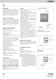
Vista frontale, comandi e led.
L
N
U1
Schema elettrico.
Pompe di circolazione, bruciatori, elettrovalvole.
L
N
Schema elettrico.
Valvole motorizzate.
CHIUDE
APRE
RAEE - Informazione agli utilizzatori
Il simbolo del cassonetto barrato riportato sull’apparec-
chiatura o sulla sua confezione indica che il prodotto alla
fine della propria vita utile deve essere raccolto separa-
tamente dagli altri rifiuti. L’utente dovrà, pertanto, confe-
rire l’apparecchiatura giunta a fine vita agli idonei centri
comunali di raccolta differenziata dei rifiuti elettrotecnici
ed elettronici. In alternativa alla gestione autonoma, è
possibile consegnare gratuitamente l’apparecchiatu-
ra che si desidera smaltire al distributore, al momento
dell’acquisto di una nuova apparecchiatura di tipo equi-
valente. Presso i distributori di prodotti elettronici con
superficie di vendita di almeno 400 m
2
è inoltre possibile
consegnare gratuitamente, senza obbligo di acquisto,
i prodotti elettronici da smaltire con dimensioni inferiori
a 25 cm. L’adeguata raccolta differenziata per l’avvio
successivo dell’apparecchiatura dismessa al riciclaggio,
al trattamento e allo smaltimento ambientalmente com-
patibile contribuisce ad evitare possibili effetti negativi
sull’ambiente e sulla salute e favorisce il reimpiego e/o
riciclo dei materiali di cui è composta l’apparecchiatura.
Viale Vicenza, 14
36063 Marostica VI - Italy
www.vimar.com
49400975A0 05 2203
PLANA
14440
Heating/air conditioning slide switch
LED indicating the state of the relay
and/or presence of supply
“Energy saving”
LED activated
Temperature setting
DESCRIPTION.
Electronic thermostat for ON/OFF ambient temperature
control (heating and air-conditioning), summer/off/win-
ter switch, class I temperature control device (contribu-
tion 1%), input for remote activation of energy-saving
function, change-over relay output 6(2) A 230 V~,
power supply 230 V~ 50/60 Hz - 2 modules.
SCOPE.
The thermostat is suitable for ambient temperature
control by regulating the supply circuit of the burner
or heat pump (heating), or the supply circuit of the air
conditioner (air conditioning), with remote activation,
of the “energy saving” function, including on a timer
if desired.
CHARACTERISTICS.
Supply voltage: 230 V~ ±10% 50-60 Hz
Average absorption: 3 VA
Output: 6(2) A 230 V~ change-over relay output
Type of regulation: ON/OFF
Hysteresis: 1 °C
Thermostat operating range: +10 °C - +30 °C
• With knob at minimum the “antifreeze” function is
active (+6 °C)
Terminal for the remote enabling (if necessary, it can
be time-delayed) of the “energy saving” function
• “Energy saving” function: the set temperature is
reduced of 4 °C (heating), or increased of 4 °C (air
conditioning)
Protection degree: IP40
Class II equipment:
Number of manual cycles: 3.000
Number of automatic cycles: 100.000
Type of contact opening: micro-disconnect
Type of action: 1B
Tracking index: PTI175
Pollution degree: 2 (normal)
Voltage pulse: 4.000 V
• Ambient temperature range during transport: -25 °C +60 °C
Operating temperature: 0 °C +40 °C
ErP classification (Reg. EU 811/2013): class I, con-
tribution 1%
Software class and structure: A
INSTALLATION.
The thermostat must be installed in flush or surface
mounting boxes with Plana mounting frames and cover
plates at a height of 1,5 m above floor level, in an
appropriate position for measuring the ambient tem
-
perature; do not position the instrument inside niches,
behind doors and curtains, close to heat sources or
in areas influenced by outside weather conditions. In
particular, it should not be installed on perimeter
walls or near electrical devices which generate heat
(e.g. dimmers or lamps).
The thermostat is designed for use in dry, dust-free
areas with an ambient temperature between 0 °C and
+40 °C.
USING THE ELECTRONIC THERMOSTAT.
• Set the desired program through the frontal slide
switch : OFF
- OFF position: the thermostat is switched off
- HEATING position : the relay output is active when
the ambient temperature is lower than the set tem-
perature
- AIR CONDITIONING position : the relay output is
active when the ambient temperature is higher than
the set temperature
• To set the comfort temperature, place the pointer
of the knob at the value of the desired temperature
(which is marked on the knob itself)
Green/yellow bicolour LED :
- the green LED shows that the relay output is not
active (the set temperature has been reached).
- the yellow LED shows that the relay output is active
(the set temperature has not been reached).
Anyway, when the LED lights up (green or yellow), it
shows the presence of supply.
• Green LED : when lighted shows the functioning of
the “energy saving” function
To activate the “energy saving” function you have
to connect the terminal
to the mains through an
external manual or automatic switch (e.g. timer). The
automatic switch allows to centralize the control of
more than one thermostat.
When the function is active, the thermostat sets a
temperature 4°C lower than the one selected through
the knob (in heating) or higher (in air conditioning).
INSTALLATION RULES.
Installation should be carried out by qualified personnel
in compliance with the current regulations regarding the
installation of electrical equipment in the country where
the products are installed.
CONFORMITY TO STANDARDS.
LV Directive.EMC Directive.
Standards EN 60730-1, EN 60730-2-9.
REACH (EU) Regulation no. 1907/2006 Art.33. The
product may contain traces of lead.
Front view and view of controls.
L
N
U1
Electrical diagram.
Circulation pumps, burners, solenoid valves.
L
N
Electrical diagram.
Motor-operated valves.
CLOSE
OPEN
RAEE - Informazione agli utilizzatori
If the crossed-out bin symbol appears on the equipment
or packaging, this means the product must not be inclu-
ded with other general waste at the end of its working
life. The user must take the worn product to a sorted
waste center, or return it to the retailer when purchasing a
new one. Products for disposal can be consigned free of
charge (without any new purchase obligation) to retailers
with a sales area of at least 400 m
2
, if they measure less
than 25 cm. An efficient sorted waste collection for the
environmentally friendly disposal of the used device, or its
subsequent recycling, helps avoid the potential negative
effects on the environment and people’s health, and en-
courages the re-use and/or recycling of the construction
materials.


Produkt Specifikationer

Mærke: Vimar
Kategori: Termostat
Model: 14440.SL

Har du brug for hjælp?

Hvis du har brug for hjælp til Vimar 14440.SL stil et spørgsmål nedenfor, og andre brugere vil svare dig


Termostat Vimar Manualer

Vimar

Vimar 02973 Manual

25 Juli 2025
Vimar

Vimar 19440.M Manual

24 Juli 2025
Vimar

Vimar 01910.14 Manual

24 Juli 2025
Vimar

Vimar 02952.BN Manual

24 Juli 2025
Vimar

Vimar 02970 Manual

24 Juli 2025
Vimar

Vimar 14440.SL Manual

24 Juli 2025
Vimar

Vimar 14446 Manual

24 Juli 2025
Vimar

Vimar 02971.M Manual

24 Juli 2025
Vimar

Vimar 02973.N Manual

24 Juli 2025

Termostat Manualer

Nyeste Termostat Manualer